An Introduction to Reflow Soldering and Soldering Methods
The objective of this article is to explain the best techniques for soldering sensors manufactured by Merit Sensor using automated equipment. All profiles must be assessed and tested for best performance.
Due to concerns over the safety of lead and new regulations prohibiting its use, such as the Restriction on Hazardous Substances (RoHS) Directive in Europe, an increasing number of companies have stopped using conventional tin-lead (Sn/Pb) solder in the manufacture of circuit boards. The RoHS Directive has banned the European sale of new electrical and electronic equipment containing more than the specified levels of cadmium, hexavalent chromium, lead, mercury, polybrominated biphenyl (PBB), and polybrominated diphenyl ether (PBDE) flame retardants.
Merit Sensor provides pressure sensors that are fixed on ceramic substrates and are RoHS compliant. The lead-free solder pads are plated with AgPt to assure an excellent solder joint for most PCB connections.
Merit Sensor parts can be soldered using either Pb-containing or Pb-free solder process. The aim of this article is to guide customers on how to solder Merit Sensor parts using either Pb-free solder or Pb-containing solder.
In order to meet the RoHS directive, products must be soldered with Pb-free solder.
Soldering with Pb-Free Solder
As the pressure sensors from Merit Sensor are fabricated on ceramic, a Pb-free solder should be chosen that is well-suited with the solder pads. Merit Sensor suggests using solder alloys with SnAgCu that have a melting point of 217-221 °C. Table 1 shows the Pb-free solder alloys in the SnAgCu family.
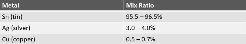
Table 1. Pb-free solder alloys of the SnAgCu family
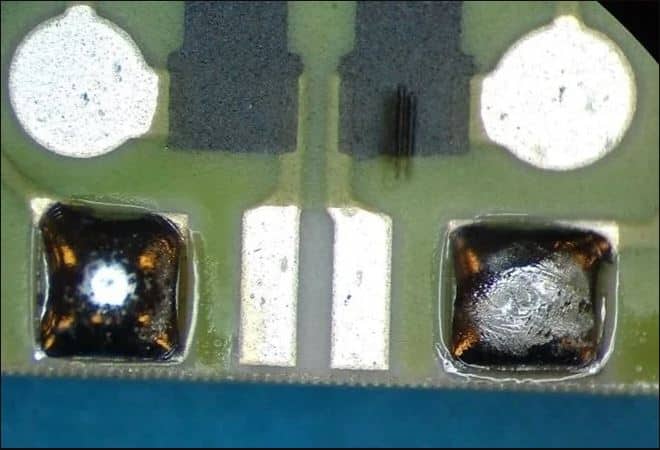
The surface of Pb-free solder alloys can appear significantly different when compared to Pb-containing solder (See Figure 1). Additionally, when compared to a Pb-containing solder joint, a Pb-free solder joint will have a dull or matte finish. This is because the surface of the solder joint will become rough when Pb-free alloys begin to cool. This roughness is attributed to the increased volume contraction of the Pb-free alloys. Compared to the Pb-containing solder joints, the Pb-free solder joints are often smaller but this would have no effect on the reliability as these are simply cosmetic characteristics.
Figure 1. Examples of a Pb-containing solder joint (left) and a typical finished surface of a Pb-free solder joint (right).
A reflow soldering profile for Pb-free soldering demands a higher melting point when compared to Pb-containing solders. The temperature differences on the board should be reduced because the process time for Pb-free solder is less than Pb-containing solder. Due to this fact, Merit Sensor does not recommend IR Reflow systems for Pb-free soldering, and instead suggests using forced convection reflow systems to ensure a successful Pb-free reflow soldering.
The pressure sensors offered by Merit Sensor can be soldered with profiles that are based on the standard IPC/JEDEC J-STD-020C (January 2004). For identifying the best temperature profile, each process must be assessed. The best temperature profile is defined by the board and the solder paste used.
The recommended profile according to IPC/JEDEC J-STD-020C is shown in Table 2 and Figure 2.

Table 2. Pb-free classification reflow profile according to IPC/JEDEC J-STD-020 C
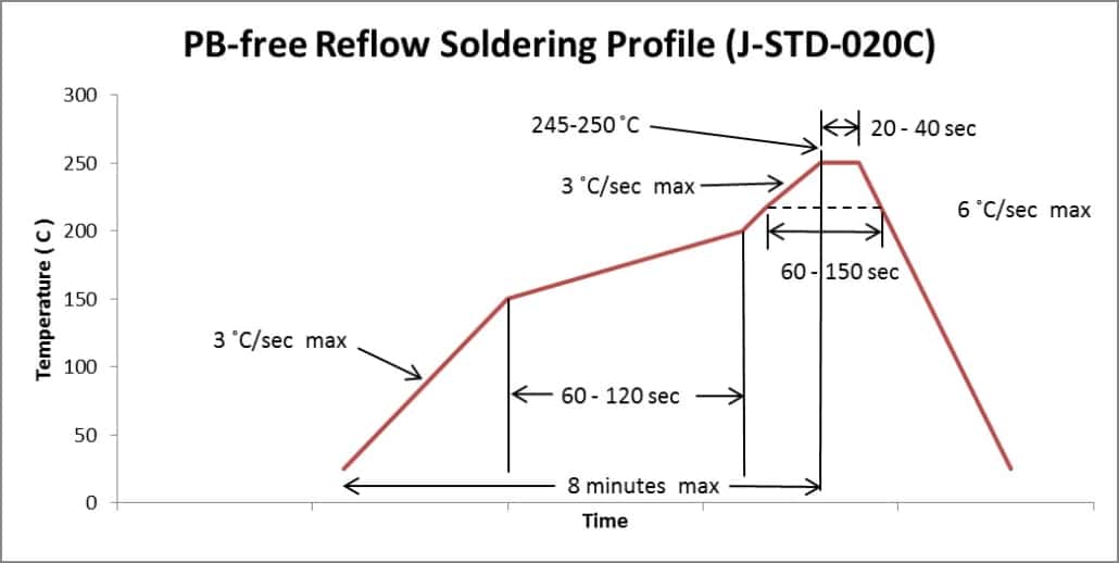
Figure 2. Pb-free Classification reflow profile according to IPC/JEDEC J-STD-020.
Use of nitrogen — It may be essential to work in nitrogen if air leads to unsatisfactory solder joints due to increased temperature and oxidation of Pb-free solder; however, the majority of Pb-free solder pastes can be used in air. Nitrogen may be used if the solder joints do not have adequate wetting.
Hand Soldering — Merit Sensor does not recommend hand soldering. An excess amount of energy is required for Pb-free soldering when compared to Pb-containing solder alloys. The heat transfer to the solder joint is critical and should never be tried with a soldering iron.
When using a soldering iron, it should be remembered that Pb-free soldering needs a rapid heat transfer to attain a successful solder joint. It may need an increased tip temperature to 360-390 °C and/or a longer period. Use of solder stations of at least 80 watts of power is highly recommended. Pre-heating can be used to decrease the amount of heat caused on the surrounding components during hand soldering, as is done with reflow soldering.
Soldering Pressure Sensors with Pb-Containing Solder
Temperatures should not go beyond 225 °C for 30 seconds if Pb-containing solder is employed. Merit pressure sensors should be soldered with “no-clean” type solder paste which contains 62%Sn36%Pb2%Ag and has a melting point of 179 °C. The solder paste containing 2%Ag significantly reduces the migration of silver from the AgPt pad into the solder paste. Conversely, it is not advisable to use 63%Sn37%Pb solder paste. Table 3 and Figure 3 show the proper reflow profile for SnPb solder.
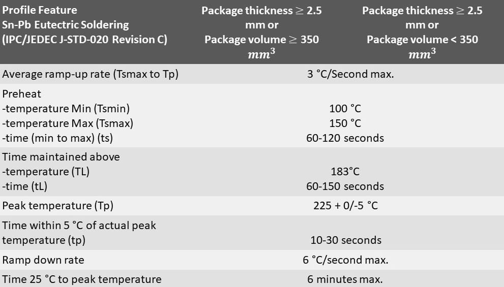
Table 3. SnPb classification reflow profile according to IPC/JEDEC J-STD-020C
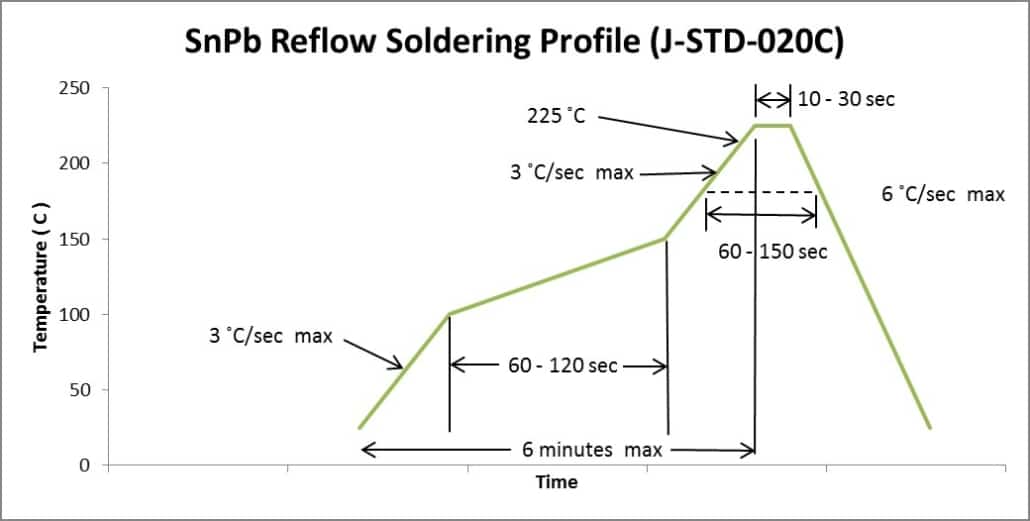
SnPb Classification reflow profile according to IPC.EDEC J-STD-020C.
If the reflow process is followed correctly, then the solder joint should be able to cover the whole solder pad of the ceramic PCB (See Figure 4–left). In most cases, manual soldering will lead to overheating of the device because of the ceramic’s high thermal conductivity. Very low temperatures will lead to partial soldering, that will further lead to a weak connection to the PCB as can be observed in Figure 4 (middle and right). The solder joint in the middle is an example of an adequate solder. However, that solder failed to wet out and cover the whole pad. The joint on the right was exposed to low heat and inadequate solder, which resulted in unsatisfactory pad coverage and also a weak joint as the solder balled up. It is advised to attach a thermocouple to the sensor to optimize the solder profile and ensure that none of the maximum temperatures are surpassed.
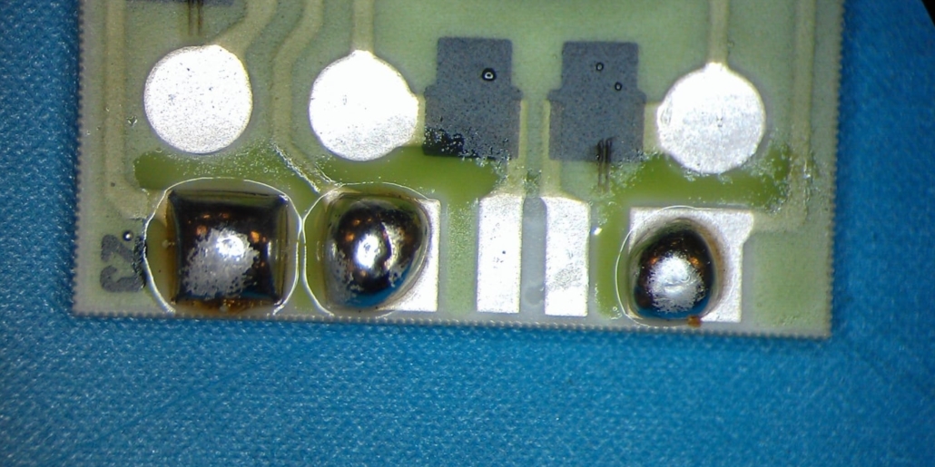
Figure 4. Example of good solder joint (left) and bad solder joints (middle and right).
Stress Normalization Delay for Calibration
For best results, Merit Sensor recommends that any surface mount pressure sensor be allowed to rest at room temperature for at least 48 hours prior to calibration. The stress induced by reflow soldering will usually normalize within this period and help improve product calibration.
For more information, visit this article on AZONetwork.com