Sensor Modules – Uncompensated But Cost-Efficient
The choice of components in a system, including pressure sensors, is significantly affected by price efficiency. If the components exactly fit into the application without the addition of irrelevant cost or value, then it is possible to achieve the best results. The research on various sensor module configurations led to the discovery of an uncompensated configuration — pressure sensor without signal conditioning and any offset and span thermal shifts correction—that can offer the best cost-performance choice.
Generally, the advantages for an uncompensated sensor are as follows:
- Good signal for sensitivity/level, linearity, hysteresis
- Faster signal conversion
- Signal conditioning cost saving
- Low voltage capability with less energy consumption
- High sensitivity/resolution
A step-by-step approach to analyzing your application and requirements will help in making the appropriate decision.
Step 1: Sensor Surrounding Check
In the majority of cases, a digital or A/D input is available in the circuit. If that function is already present, then paying for it again in a compensated sensor, particularly if the existing input already provides higher resolution and conversion timing is unnecessary. An uncompensated output signal is high enough even at low pressure in a large number of cases. For example, at 1 psi a bare die delivers generous 40 mV output @ 5 Vdc (See Figure 1).
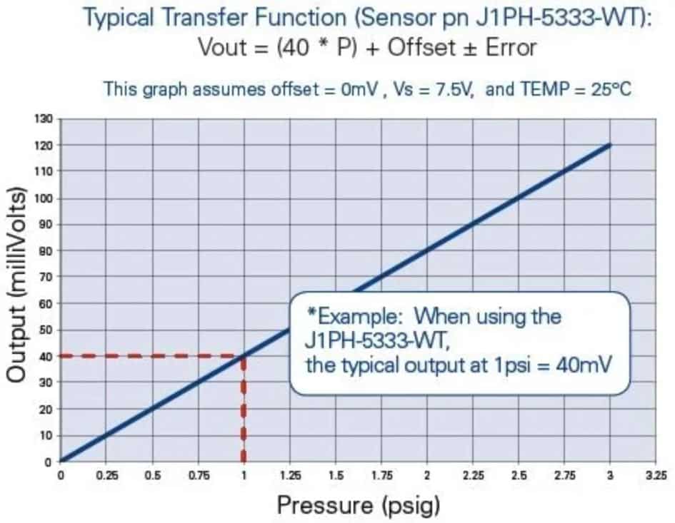
Figure 1. Merit Sensor J-Series (1..300 psi range) transfer function.
The ability to work with extremely low power supply voltage, starting from 1.0 Vdc, is another feature of the uncompensated configuration. This adds the extra benefits of quick power-up time, low self-heating effects and low power consumption, which all have to be considered in battery-driven applications, for instance.
Step 2: Define the Limit
It is important to define the signal accuracy requirement. Since the uncompensated signal comes from the bare die without compensation, a number of parameters should be taken into consideration for final error calculation, including TCS (temperature coefficient of sensitivity), TCO (temperature coefficient of offset), sensitivity and linearity.
The sensitivity (mV/V) value determines if the front end of the conditioner — a microprocessor or microcontroller – works correctly. It defines the resolution of the measurement, along with the available bits (A/D converter). An A/D converter up to 16 bit can be used without any difficulty due to the exceptional signal-to-noise ratio. However, signal calibration is necessary as the bare die has a sensitivity spread. The typical sensitivity value differs +/-10% from one batch to another and within 5% within the same batch and wafer.
The signal error is directly affected by linearity. Depending on the MEMS signal characteristics, it can be compensated easily if the final accuracy is tight. Generally, the non-linearity error is usually less than 0.2% at the midpoint of the pressure range based on Best Fit Straight Line (see Figure 2). The non-linearity error can be compensated to achieve better than 0.2% by introducing a third pressure point.
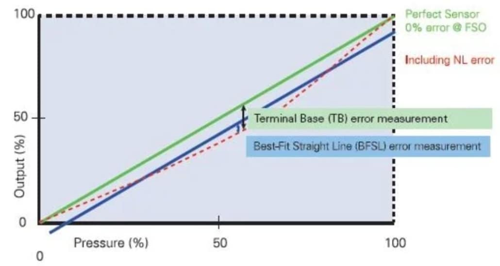
Figure 2. By adding a third pressure point, non-linearity errors can be compensated to achieve better than 0.2%.
Repeatability and hysteresis, which are typically less than 0.05%, are two parameters coming from the bare MEMS die that cannot be compensated. The impact of these two parameters is generally insignificant as it is pertains to the overall accuracy specification.
At a fixed temperature, the following errors should be taken into consideration when compensating a MEMS element:
- +/- Offset: pressure calibration at zero with 1 point
- +/- Signal (spread): pressure calibration with 2 points
- +/- Linearity: pressure calibration with 3 points
- +/- Hysteresis/ repeatability: Typical error less than 0.05%
Another key parameter required to complete the error calculation would be operating temperature. The thermal error should be calculated in order to determine if temperature compensation is needed. The example given below demonstrates a simple case where the temperature error is 0 to +50 °C.
- Example: Temperature range: 0 to +50 °C with respect to ambient temperature (25 °C), the maximum delta is: 50-25 = 25 °C
- Max. Offset drift (TCO): +/- 0.25% FS/ °C * 25 °C = +/- 6.25% FS
- Max. Span drift (TCS): -2200 ppm = -0.22% FS/ °C * 25 °C = -5.5% FS
- Total temperature drift error: +6.25% FS/ °C, -13.25% FS/ °C (worst case)
Note: TCS is always negative and could be compensated as a fixed value for at least half of the value and with a defined algorithm.
If temperature compensation is needed, then there are a couple of basic options available to help achieve one’s accuracy requirements.
Step 3: Calibration/Compensation Process
Depending on the requested error calculation and calibration, the next step is to define whether the requested process can be carried out and where it will be performed. Temperature compensation and pressure calibration have different impacts on the manufacturing process. In either case, both steps can be outsourced or performed in-house during the manufacturing process.
As a pressure test may already be present at the manufacturing site, this step could be used for the pressure calibration. In contrast, temperature compensation requires specific equipment and know-how. The uncompensated sensor requires accurate and stable temperature management to ensure a constant and safe compensation process. This typically needs process time and an easy way to pressurize the sensor, for example, if the span thermal shift has to be compensated.
Conclusion
Developers will be able to make the right decision between a compensated and uncompensated sensor if the required accuracy and exact operational temperature limits are defined. MEMS sensors have an important TCS and TCO and this can result in a decision to implement temperature compensation, which in some cases can incur heavy costs.
Whereas, if the total error is within the expected accuracy, a simple one pressure point calibration in combination with one temperature compensation guarantees high resolution, fast response time, low power and eventually low cost.
Application
Uncompensated sensors from Merit cover an extensive pressure range from 10 mbar up to 35 bar and can be employed to measure air and non-corrosive liquids and gases. The temperature range is broad, which makes the parts ideal for many applications. An automatic placement machine handles the package and the same can be soldered using lead-free reflow process.
Due to the narrow temperature range in the medical field (0 to 50 °C), uncompensated sensors work well in applications such as blood-pressure monitors, inflation devices, hospital gases, vacuum monitoring and liquids pressure, air/flow (respirators) measurement.
For the consumer and industrial industries, many applications with moderate to extended temperature ranges such as water pressure monitoring, building/clean room pressure monitoring and filter block detection, use uncompensated sensors as the pressure and temperature calibration is already incorporated into the final product.
For more information, visit this article on AZOSensors.com
