Bridge Configurations for Pressure Sensors
This article describes bridge configurations of different pressure sensors, when each can and cannot be used, and the pros and cons of each.
Introduction
Wheatstone bridge is the core of Merit Sensor’s pressure sensors and is comprised of a group of four resistors on a silicon etched diaphragm. When pressure is applied to the diaphragm, the resistors are stressed which changes their resistance.
In an ideal setting, all of the resistors would be perfectly matched and fully independent of temperature.
However, practically, differences exist between the resistance values of each resistor. Moreover, temperature also changes resistor values. The change to resistor values and the overall bridge output caused by temperature is called the Temperature Coefficient of Resistance, or TCR.
A pressure sensor operating independently of temperature is needed in many applications. Such applications require the compensation of the pressure sensor’s TCR.
TCR compensation can be done in two general methods – passive and active. In passive compensation, values of each bridge resistor must be measured in order to determine the values required for the compensation resistors.
In active compensation, an analog circuit, a microcontroller, or signal conditioner records the bridge output across various pressure and temperature conditions and adjusts sensor outputs accordingly.
Bridge Configurations
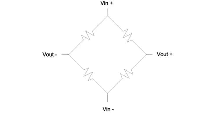
a. Closed – A bridge in which all resistors are connected (See Figure 1).
Figure 1. Closed bridge.
In a closed bridge, individual resistors cannot be measured because the other three resistors of the bridge will always have an influence over them.
b. Half Open – A half open bridge is divided into two branches and connected at one end (See Figure 2).
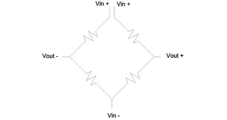
Figure 2. Half open bridge.
Unlike closed bridge, a half open bridge allows for each resistor to be measured, which is an advantage if the performance of the sensor needs to be determined. In addition, a half open bridge enables the addition of either active or passive compensation as required.
An additional electrical connection is needed by a half open bridge.
c. Full Open – A full open bridge is divided into two branches, and is open at both ends (See Figure 3).
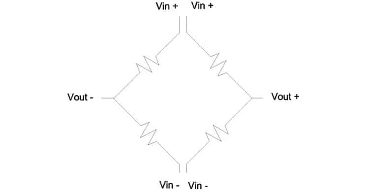
Figure 3. Full open bridge.
Just as half open bridge, the full open bridge also enables the measurement for each resistor. It can use either active or passive compensation. Additionally, each half of the bridge can be powered and measured independently which is an advantage because some signal conditioners commonly used in pressure sensor applications require two independent branches.
However, the full open bridge configuration needs an additional electrical connection which is beyond that required by the half open configuration.
Examples of Implementations
a. Closed – As it is not possible to measure the individual resistors in a closed bridge, it can be used with active compensation or in an application where sensor output fluctuations caused by temperature changes are acceptable.
A closed bridge with active compensation is shown in Figure 4.
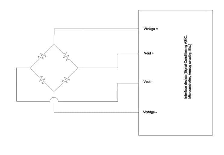
Figure 4. Closed Bridge with Interface device (Signal Conditioning ASIC, Microcontroller, Analog circuitry, Etc.)
A pressure switch is one example of a suitable application for a closed bridge, where temperature independence is not critical. Here, knowing that a pressure threshold has been reached is more important than measuring the absolute pressure.
b. Half Open – As shown in Figure 4, active compensation can be applied to the half open bridge. Similarly, passive compensation can also be applied to the half open bridge as shown in Figure 5.
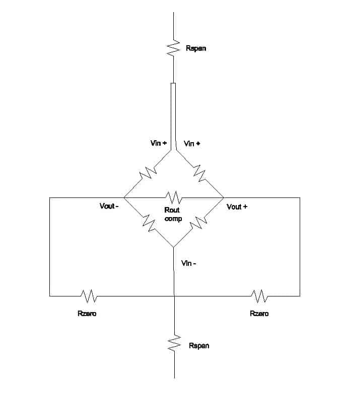
Figure 5. Half open bridge with passive compensation.
Figure 5 shows the implementation of a half open bridge with passive compensation, indicating that added components and the extra electrical connection (Vin+) are needed to close the bridge. Just as the name conveys, additional resistors accomplish span, zero and output impedance compensation. These components have to be added after taking the open bridge measurements at the required conditions.
c. Full Open – The full open bridge has an extensive range of implementations. Apart from being used as a full open bridge, the full open bridge can be used as a closed (Figure 4) or a half open bridge (Figure 5). Figure 6 shows how a full open bridge could be used for two functions – pressure and temperature.
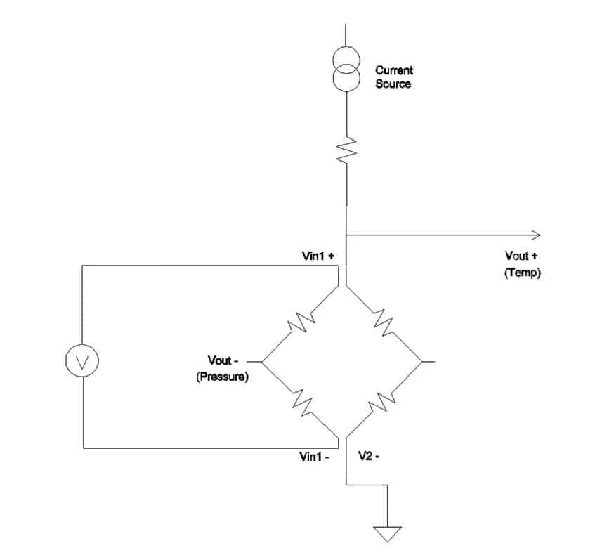
Figure 6. Full open bridge with two functions.
In this implementation, half of the bridge is being used as a pressure sensor and the other is being used as a temperature sensor. As there is only the voltage swing of half the bridge, only half the pressure output signal will be present. However, this provides the additional benefit of measuring the actual die temperature. When compared to an ambient temperature measurement, this temperature measurement will allow for a more accurate input for temperature compensation.
Choosing the Appropriate Configuration for an Application
It is necessary to consider the entire sensing system when making decisions about the bridge configuration. First, users must decide if temperature independence is significant. If it is important, then they must decide whether passive or active compensation will be used. If active compensation is selected and a signal conditioner or other electronic device will be used, it should meet that device’s requirements. Care must be taken as devices with similar functions may have very different requirements.
As discussed before, each configuration has its own advantages and disadvantages. Although the added electrical connections of a full open bridge add to the complexity of assembly, it allows for more flexibility and also provides the ability to troubleshoot bridge issues more easily.
Eventually, the bridge configuration must be chosen based on a thorough analysis of the system.
For more information, visit this article on AZOSensors.com