The Wheatstone Bridge
Introduction to the Wheatstone Bridge
The heart of Merit Sensor’s pressure sensors is a Wheatstone bridge that is comprised of a group of four resistors on a silicon etched diaphragm. As pressure is applied to the diaphragm the resistors are stressed, changing their resistance.
In an ideal setting, all of the resistors would be perfectly matched and completely temperature independent.
In the real world, however, differences exist between the resistance values of each resistor. In addition, temperature also changes resistor values. The change to resistor values and the overall bridge output due to temperature is known as the Temperature Coefficient of Resistance, or TCR.
Many applications require that a pressure sensor operate independently of temperature. In these applications, the pressure sensor’s TCR must be compensated for.
There are two general methods for TCR compensation – passive and active.
In passive compensation, the individual bridge resistor values will need to be measured in order to determine values needed for the compensation resistors.
In active compensation, a microcontroller, signal conditioner or analog circuit records the bridge output across various temperature and pressure conditions and adjusts sensor outputs accordingly.
Bridge configurations
a. Closed – A bridge in which all resistors are connected (See Figure 1).
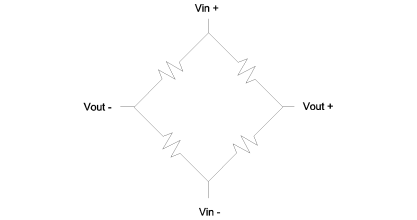
Figure 1 – Closed bridge
In a closed bridge there is no way to measure individual resistors as there will always be influences from the other three resistors of the bridge.
b. Half Open – A bridge that is divided into two branches and connected at one end (See Figure 2).
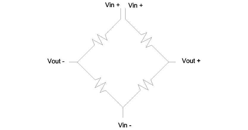
Figure 2 – Half open bridge
In contrast to the closed bridge, a half open bridge allows measurements to be taken for each resistor, which is a benefit if the sensor’s performance needs to be determined. A half open bridge also allows for either active or passive compensation to be added as needed.
A half open bridge requires an additional electrical connection.
c. Full Open – A bridge that is divided into two branches, which are open at both ends (See Figure 3).
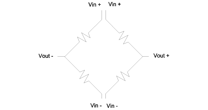
Figure 3 – Full open bridge
Similar to the half open bridge, the full open bridge allows for each resistor to be measured. In addition to being able to use either active or passive compensation, each half of the bridge can be powered and measured independently. This is beneficial as some signal conditioners commonly used in pressure sensor applications require two independent branches.
However, the full open bridge configuration requires an additional electrical connection beyond that required by the half open configuration.
Examples of Implementations
a. Closed – Since individual resistors can’t be measured in a closed bridge, a closed bridge can be used with active compensation or in an application where sensor output fluctuations due to temperature changes are acceptable.
Figure 4 depicts a closed bridge with active compensation.
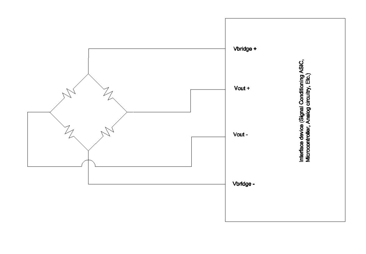 Figure 4 – Closed Bridge with Interface device (Signal Conditioning ASIC, Microcontroller, Analog circuitry, Etc.)
One example of a suitable application for a closed bridge where temperature independence is not critical is a pressure switch, where the absolute pressure measurements are not as important as knowing you’ve reached a pressure threshold.
b. Half Open – Active compensation can be applied to the half open bridge as in Figure 4 shown above. Passive compensation can also be applied to the half open bridge as seen below in Figure 5.

Figure 5 – Half open bridge with passive compensation
The implementation of a half open bridge with passive compensation in Figure 5 shows the added components as well as the extra electrical connection (Vin+) required to close the bridge. The additional resistors, as they are named, accomplish span, zero and output impedance compensation. These components need to be added after open bridge measurements have been taken at the required conditions.
C. Full Open – The full open bridge has a wide variety of implementations. In addition to being used as a full open bridge it can be used as a half open (Figure 5) or a closed bridge (Figure 4). Figure 6 is an illustration of how a full open bridge could be used for two functions – temperature and pressure.
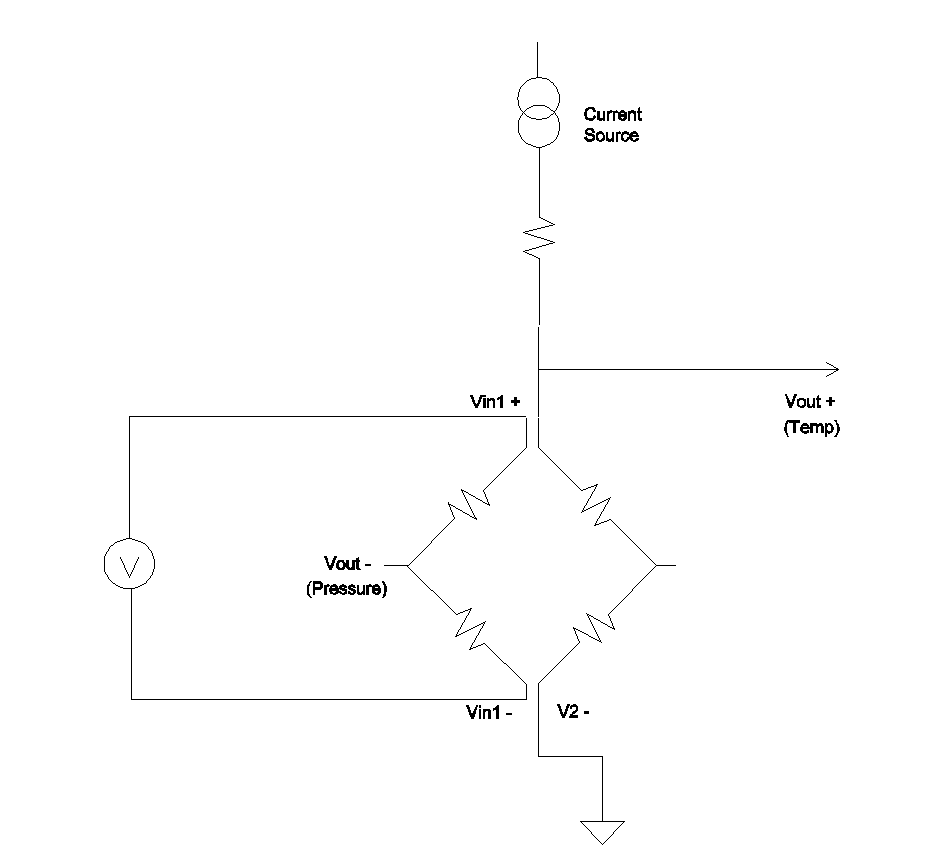
Figure 6 – Full open bridge with two functions
In this implementation, half of the bridge is being used as a temperature sensor and the other is being used as a pressure sensor. Only half the pressure output signal will be present because there is only the voltage swing of half the bridge. However, this allows for the added benefit of a means to measure actual die temperature. The temperature measurement will allow for a more accurate input for temperature compensation than an ambient temperature measurement would.
Choosing the Appropriate Configuration for your Application
The entire sensing system should be taken into consideration when making decisions about the bridge configuration. First, the user must decide if temperature independence is important and if it is, whether active or passive compensation will be used. If active compensation is chosen and a signal conditioner or other electronic device will be used, that device’s requirements must be met.
Use caution as devices with similar functions may have very different requirements.
As previously discussed, each configuration has its own benefits and drawbacks. The added electrical connections of a full open bridge add to the complexity of assembly but allow for more flexibility as well as the ability to more easily troubleshoot bridge issues.
Ultimately, the choice of bridge configuration should be based on a thorough analysis of the system.
Disclaimer Notice
Merit Sensor Systems produces high quality products that perform within the parameters of the data sheet. Typical pressure and temperature performance values are not tested 100% but they have been validated during qualification. Merit Sensor cannot guarantee that the product will function properly after mounting and post processing by the customer. It is the responsibility of the customer to test and to qualify the function of the Merit Sensor product in the final package. Customer is responsible for the required knowledge to handle product and Merit Sensor assumes no liability for consequential damages that may result in yield loss or field failures in the final application.
THE INFORMATION IN THIS DOCUMENT IS PROVIDED TO YOU “AS IS” WITHOUT WARRANTIES OR CONDITIONS OF ANY KIND, WHETHER EXPRESS OR IMPLIED. Merit Sensor Systems reserves the right to modify this document and assumes no responsibility for any failures that result from the use of this information. All information provided in this document is for illustration purposes only.