Tag Archive for: AZO Article

Pressure Sensor for Extended Temperatures

A number of pressure sensor applications in harsh environments such as industrial, automotive, aerospace and even medical equipment present developers with contradictory requirements that result in expensive compromises. Generally, these sensors are employed to measure flow, level and pressure of harsh fluids such as refrigerant, oil, gas or other caustic solvents that can damage the sensor element. Additional challenges arise as a result of extended temperature requirements, even beyond compensation for accurate pressure readings.

Aerospace and automotive specifications are particularly stringent, with operating temperature ranges as wide as -40 °C to +150 °C. And these rugged applications usually have high accuracy and reliability requirements, as component failure can result in safety risk or product recalls. To respond, equipment manufacturers depend on expensive ongoing maintenance and component replacement to work around the inherent short lifespan of the sensor.

Challenges

Despite the fact that the packaging of the sensor component is important in solving this issue, it is a challenge that has, until lately, eluded sensor manufacturers. Consider a typical use case. An automotive application such as gas or diesel fuel-line sensing requires a sealed sensor element that can be installed within the fuel line to sense pressure changes that signify a plugged fuel filter, which offers a feedback signal to the car’s computer to warn the driver. Airplane engine, valve controls and gear, and leak-detection systems or measurement and control of compressors in industrial equipment usually have similar requirements. While medical applications may not demand the pressure sensor be operated in fluids as severe as gasoline, eventually even saline solution can be corrosive, and the cleaning and sterilization process typically needs repeated contact with caustic chemicals such as bleach.

The main issue is that the adhesives that are employed to make the pressure seal and protect the sensor die and related circuitry ultimately soften in the surrounding fluid. The sensor circuitry is broken, as soon as the seal breaks, thus creating a familiar reliability failure that can be high-priced if it causes a product recall or requires regular maintenance and replacement of the sensing subsystem.

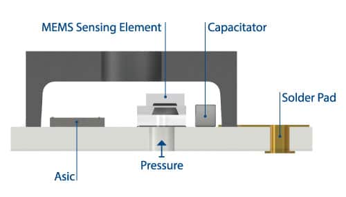
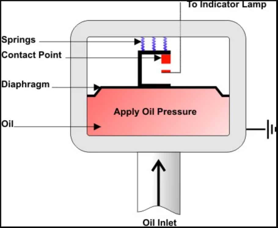
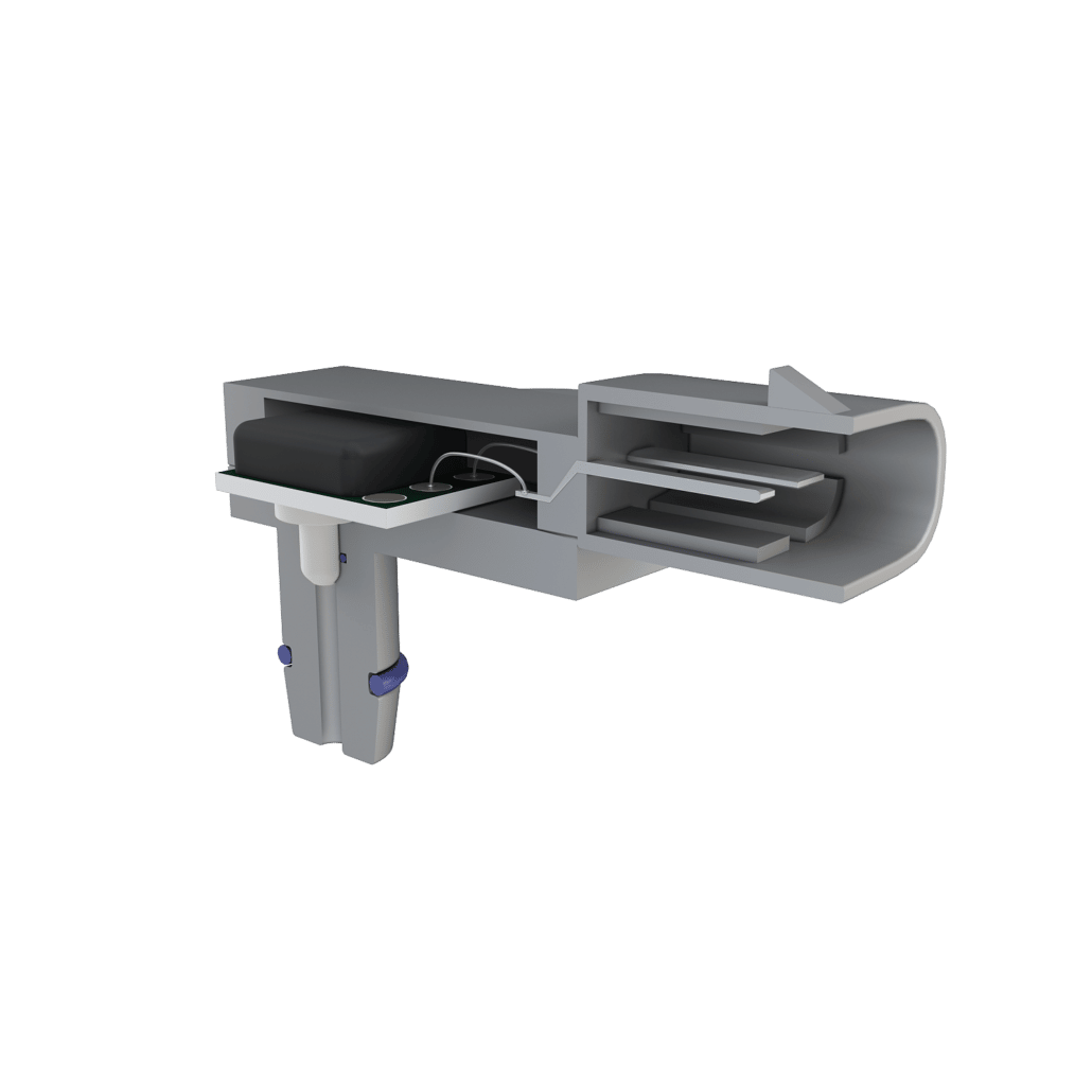
Figure 1. Sensor package showing back-side entry to protect electronic circuitry from harsh media. 

The difficulty in packaging is further increased because of the extended temperature requirements. Despite the fact that some latest adhesives are capable of withstanding higher temperatures than was feasible in the past, humidity can destroy the bond strength of most adhesives and they still risk die detachment at pressures of 300 psi. Although there are exotic epoxies that can withstand some humidity and temperature extremes, storage and application lead to additional manufacturability issues, and these epoxies are capable of affecting accuracy of the sensing element in extended temperature applications.

Solution

In order to perform well in the ranges between -40 °C to +150 °C, a pressure sensor requires a stable MEMS element as well as stable packaging and manufacturing processes. However, instability usually occurs due to differences in the TCE (thermal coefficients of expansion) of the MEMS die and the substrate on which it is mounted. Although, stainless steel might be considered a perfect substrate, its TCE is much higher than that of silicon. The metal expands and contracts, as temperature changes, while the silicon elements soldered onto it go through much smaller changes. The MEMS element reacts to the stresses caused by the TCE differences, inducing errors that seem like pressure changes to the system—thus giving system designers a new reliability issue.

An innovative new pressure sensor packaging approach creates a eutectic die bond on ceramic substrate using a gold-tin soldering alloy for a hermetic seal even at extremely wide temperature ranges, in harsh fluids and at high pressure. The ceramic substrate features a TCE that is close to silicon so there is no considerable thermal mismatch, and tin and gold are common soldering elements that adhere well to harsh fluids.

While manufacturability is affected by their high individual melting points, an alloy with a much lower melting point is produced by a gold-tin soldering bond with an 80:20 ratio. This in turn enhances manufacturability at the same time as retaining the benefits of both metals in harsh environments. Despite the fact that this gold-tin solder is more expensive than adhesive, the cost differential is small when compared to the considerable improvement in maintenance costs and long-term reliability.

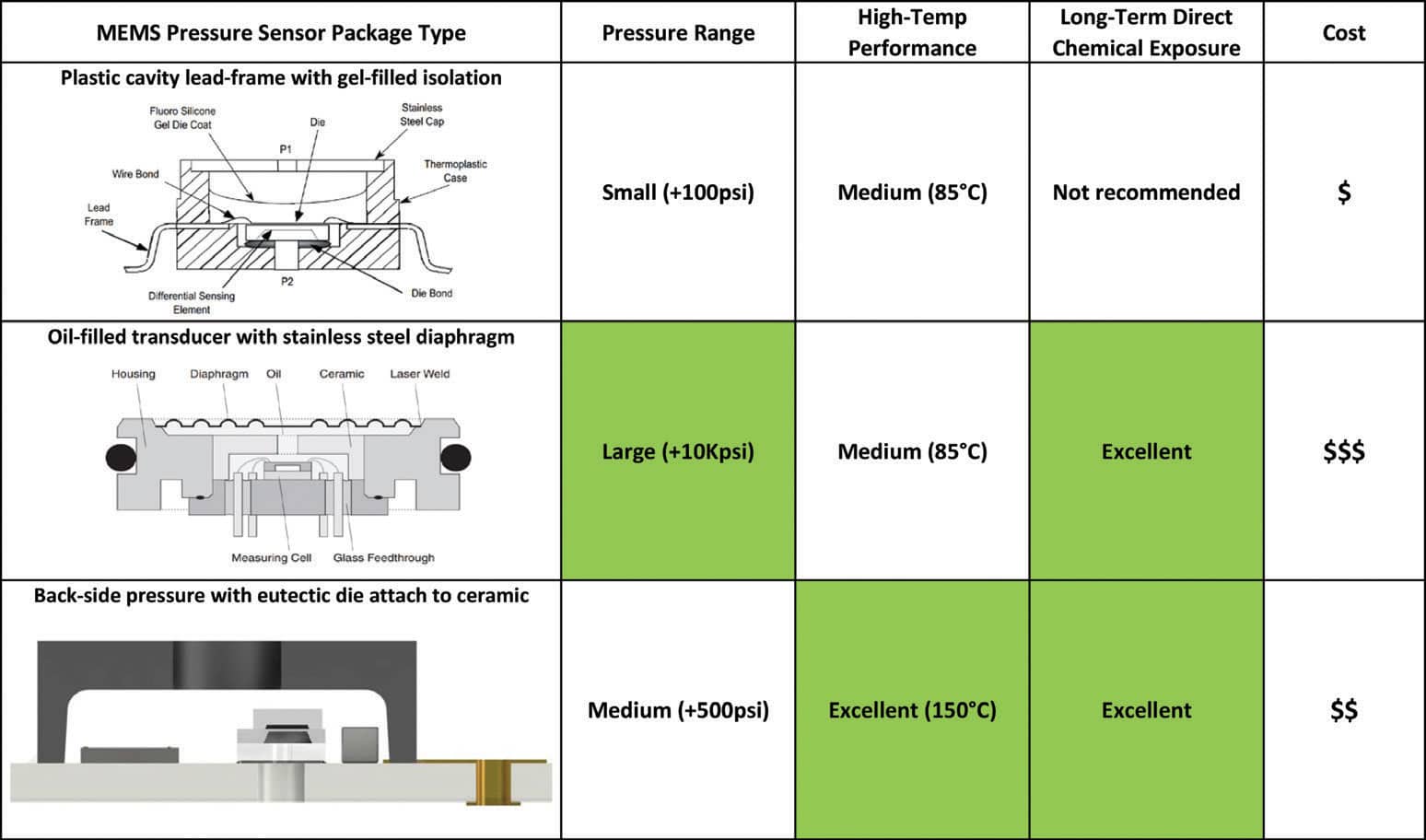
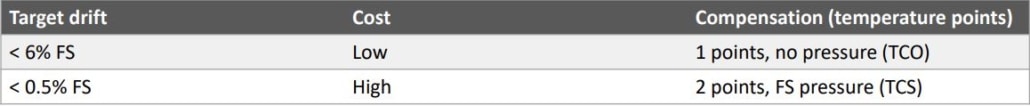
Table 1. Comparison of pressure sensor package types across harsh application requirements.

Conclusion

Checking whether the pressure media comes in at the back side or top of the sensor is an additional aspect to be considered while comparing sensor packaging approaches. The circuitry must be protected from corrosion or shorts if the pressure is on the top side of the sensor. This protection is usually achieved with a protective gel. However, a gel that is stiff enough to bear corrosive fluids is generally also stiff enough to cause stress to the MEMS element, which, again, produces sensing errors. On the contrary, back-side entry uncovers only the eutectic die attach, glass and silicon to the pressure medium—elements that have been proven to withstand these harsh environments.

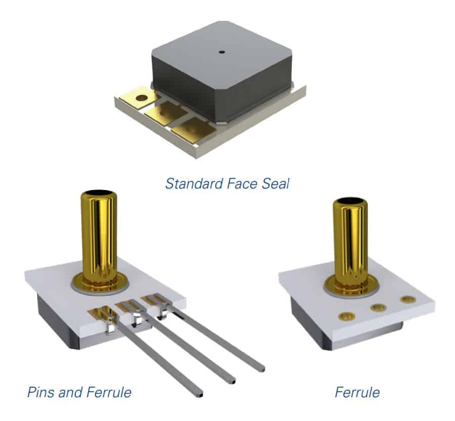
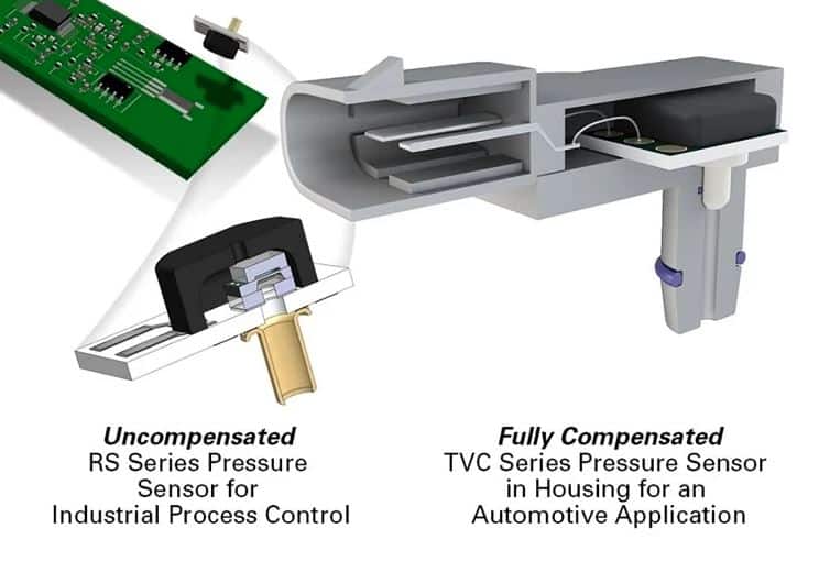
Figure 2. Merit Sensor harsh-media, extended-temperature sensors are available with optional ferrule (right), pins and ferrule (left) and standard face seal. (top).

System developers who are in need of pressure sensing abilities in extended-temperature, harsh-media applications have found that packaging is important to lower ownership cost and enhance product lifetime reliability. This challenge has been eventually resolved.

For more information, visit this article on AZOSensors.com

Sensor Modules – Uncompensated But Cost-Efficient

The choice of components in a system, including pressure sensors, is significantly affected by price efficiency. If the components exactly fit into the application without the addition of irrelevant cost or value, then it is possible to achieve the best results. The research on various sensor module configurations led to the discovery of an uncompensated configuration — pressure sensor without signal conditioning and any offset and span thermal shifts correction—that can offer the best cost-performance choice.

Generally, the advantages for an uncompensated sensor are as follows:

  • Good signal for sensitivity/level, linearity, hysteresis
  • Faster signal conversion
  • Signal conditioning cost saving
  • Low voltage capability with less energy consumption
  • High sensitivity/resolution

A step-by-step approach to analyzing your application and requirements will help in making the appropriate decision.

Step 1: Sensor Surrounding Check

In the majority of cases, a digital or A/D input is available in the circuit. If that function is already present, then paying for it again in a compensated sensor, particularly if the existing input already provides higher resolution and conversion timing is unnecessary. An uncompensated output signal is high enough even at low pressure in a large number of cases. For example, at 1 psi a bare die delivers generous 40 mV output @ 5 Vdc (See Figure 1).

Figure 1. Merit Sensor J-Series (1..300 psi range) transfer function.

The ability to work with extremely low power supply voltage, starting from 1.0 Vdc, is another feature of the uncompensated configuration. This adds the extra benefits of quick power-up time, low self-heating effects and low power consumption, which all have to be considered in battery-driven applications, for instance.

Step 2: Define the Limit

It is important to define the signal accuracy requirement. Since the uncompensated signal comes from the bare die without compensation, a number of parameters should be taken into consideration for final error calculation, including TCS (temperature coefficient of sensitivity), TCO (temperature coefficient of offset), sensitivity and linearity.

The sensitivity (mV/V) value determines if the front end of the conditioner — a microprocessor or microcontroller – works correctly. It defines the resolution of the measurement, along with the available bits (A/D converter). An A/D converter up to 16 bit can be used without any difficulty due to the exceptional signal-to-noise ratio. However, signal calibration is necessary as the bare die has a sensitivity spread. The typical sensitivity value differs +/-10% from one batch to another and within 5% within the same batch and wafer.

The signal error is directly affected by linearity. Depending on the MEMS signal characteristics, it can be compensated easily if the final accuracy is tight. Generally, the non-linearity error is usually less than 0.2% at the midpoint of the pressure range based on Best Fit Straight Line (see Figure 2). The non-linearity error can be compensated to achieve better than 0.2% by introducing a third pressure point.

Figure 2. By adding a third pressure point, non-linearity errors can be compensated to achieve better than 0.2%.

Repeatability and hysteresis, which are typically less than 0.05%, are two parameters coming from the bare MEMS die that cannot be compensated. The impact of these two parameters is generally insignificant as it is pertains to the overall accuracy specification.

At a fixed temperature, the following errors should be taken into consideration when compensating a MEMS element:

  • +/- Offset: pressure calibration at zero with 1 point
  • +/- Signal (spread): pressure calibration with 2 points
  • +/- Linearity: pressure calibration with 3 points
  • +/- Hysteresis/ repeatability: Typical error less than 0.05%

Another key parameter required to complete the error calculation would be operating temperature. The thermal error should be calculated in order to determine if temperature compensation is needed. The example given below demonstrates a simple case where the temperature error is 0 to +50 °C.

  • Example: Temperature range: 0 to +50 °C with respect to ambient temperature (25 °C), the maximum delta is: 50-25 = 25 °C
  • Max. Offset drift (TCO): +/- 0.25% FS/ °C * 25 °C = +/- 6.25% FS
  • Max. Span drift (TCS): -2200 ppm = -0.22% FS/ °C * 25 °C = -5.5% FS
  • Total temperature drift error: +6.25% FS/ °C, -13.25% FS/ °C (worst case)

Note: TCS is always negative and could be compensated as a fixed value for at least half of the value and with a defined algorithm.

If temperature compensation is needed, then there are a couple of basic options available to help achieve one’s accuracy requirements.

Step 3: Calibration/Compensation Process

Depending on the requested error calculation and calibration, the next step is to define whether the requested process can be carried out and where it will be performed. Temperature compensation and pressure calibration have different impacts on the manufacturing process. In either case, both steps can be outsourced or performed in-house during the manufacturing process.

As a pressure test may already be present at the manufacturing site, this step could be used for the pressure calibration. In contrast, temperature compensation requires specific equipment and know-how. The uncompensated sensor requires accurate and stable temperature management to ensure a constant and safe compensation process. This typically needs process time and an easy way to pressurize the sensor, for example, if the span thermal shift has to be compensated.

Conclusion

Developers will be able to make the right decision between a compensated and uncompensated sensor if the required accuracy and exact operational temperature limits are defined. MEMS sensors have an important TCS and TCO and this can result in a decision to implement temperature compensation, which in some cases can incur heavy costs.

Whereas, if the total error is within the expected accuracy, a simple one pressure point calibration in combination with one temperature compensation guarantees high resolution, fast response time, low power and eventually low cost.

Application

Uncompensated sensors from Merit cover an extensive pressure range from 10 mbar up to 35 bar and can be employed to measure air and non-corrosive liquids and gases. The temperature range is broad, which makes the parts ideal for many applications. An automatic placement machine handles the package and the same can be soldered using lead-free reflow process.

Due to the narrow temperature range in the medical field (0 to 50 °C), uncompensated sensors work well in applications such as blood-pressure monitors, inflation devices, hospital gases, vacuum monitoring and liquids pressure, air/flow (respirators) measurement.

For the consumer and industrial industries, many applications with moderate to extended temperature ranges such as water pressure monitoring, building/clean room pressure monitoring and filter block detection, use uncompensated sensors as the pressure and temperature calibration is already incorporated into the final product.

Figure 2. MS-Series, uncompensated sensor (1 to 35 bar G/A).


For more information, visit this article on AZOSensors.com

Inside a Car – Oil Pressure Sensor

Examples of a basic automobile go back as early as the 1700s, with the design and engineering of steam-powered engines, built to transport humans. By 1806, the automobile industry started the production of engines running on fuel such as gasoline and petrol. Since 1985, the revolution of car design has resulted in creating a machine that is intuitive enough to make transportation as smooth and sophisticated as possible.

Modern-day vehicles – whether these take the form of a car, motorcycle, truck, aircraft, or boat – will all have an array of sensors embedded within the skeleton of a vehicle to animate and bring a fuel-powered structure to life. The scope of this article discusses oil pressure sensors as one particular sensor type in an automobile.

Functional Principle

Standard oil pressure sensors work by displaying a warning signal when the oil pressure falls outside of the set range. Two important components to the oil pressure sensor include the spring-loaded switch and a diaphragm. The spring-loaded switch is connected to the diaphragm that is exposed to the oil pressure.

The pressure switch is mounted onto the side of an engine block and wired to an oil gallery. As the force of the oil pressure starts to build on the diaphragm, this force overcomes the switch spring pressure, which then pulls apart the electrical contacts to turn on the warning light. If the oil pressure falls below the set limit, the diaphragm releases pressure off the springs to close the switch contacts that would normally result in the display of a warning sign to the driver (Figure 1).

Figure 1. Working mechanism to an oil pressure sensor system. Image Credit: Clemson University

The low oil pressure indicator light is displayed on the dashboard of a vehicle. Any driver will know that when this light flashes continuously, it is indicating a momentary drop in the oil pressure. However, if this light remains switched on, the driver is alerted to a complete loss of oil pressure. So, when the engine to a vehicle is switched on, an electrical current travels from a fuse and straight to the oil pressure switch, making sure that the indicator light is ‘off’. When oil pressure starts to rise above 4.3 psi (per square inch), the diaphragm moves apart the contacts, thus switching on the oil pressure light.

Pressure Gauge Sensor

A low oil pressure warning light is one method used to alert the driver to fluctuations in the oil pressure levels. An alternative system for this purpose is known as a mechanical type pressure gauge component. There is a Bourdon tube inside a pressure gauge that tends to straighten out upon receiving pressure via a copper tubular component. The Bourdon tube is attached to a needle on the gauge, which moves as the tube begins to take a different shape. Movement of the needle across a scale on the gauge is used as a reference point to indicate changes in oil pressure inside the engine to a vehicle.

Sources and Further Reading

  • Ribbens, W.B., Mansour, N.P. (2003). Understanding Automotive Electronics. USA, Massachusetts: Elsevier Science.
  • Schwaller, A.E. (2005). Total Automotive Technology. USA, New York: Thomson and Delmar Learning.
  • Hillier, V., Coombes, P. (2004). Fundamentals of Motor Vehicle Technology. UK, Cheltenham: Nelson Thornes Ltd.
  • Knowles, D., Erjavec, J. (2005). TechOne: Basic Automotive Service and Maintenance. USA, New York: Thomson Delmar Learning.

For more information, visit this article on AZOSensors.com

Compensated and Uncompensated Pressure Sensors

Take a look at Merit Sensor’s product portfolio, and you will see that the pressure sensors are available fully compensated, passively compensated, and uncompensated. Let’s briefly review the differences.

When signal conditioning is used to compensate for a sensor’s non-ideal output, the sensor is considered fully compensated. When laser-trimming technology is used to change a sensor’s resistor properties and performance, the sensor is considered passively compensated. And when a sensor comprises nothing more than a MEMS die bonded on a ceramic substrate and wire bonded to the metal traces on the ceramic but has no signal conditioning and no laser-trimmed resistors, the sensor is uncompensated.

The application in which a pressure sensor is used often determines whether the customer needs the sensor to be fully compensated, passively compensated, or uncompensated. For example, in monitoring blood pressure, a pressure sensor is exposed to only a narrow temperature range around room temperature. A passively compensated pressure sensor is accurate enough for the application. In monitoring pressure in the fuel rail of an automobile, however, the pressure sensor needs to be able to function accurately and consistently in much wider temperature ranges. It is also only one of many different parts assembled in volumes too large to do compensation in line. A fully compensated pressure sensor is ideal for this application. But to measure variable air volume in a building, a customer could purchase a pressure sensor uncompensated because the pressure sensor would likely be integrated into the control board, where the compensation could be done.

Fully Compensated TVC Series Pressure Sensor in Housing

There is also the issue of packaging the pressure sensor, i.e. integrating it into a housing. If a customer’s packaging process introduces significant stress to the sensor, a compensated sensor would register a new zero point, and the compensation would be flawed. In this case the customer should consider purchasing an uncompensated sensor and then compensating it, or having it done by a specialist, once the sensor has been completely integrated into the final module.

Pressure-sensor compensation is challenging and costly, though. It requires specialized equipment and expertise. Perhaps most important, it is time consuming. Each sensor needs to be calibrated individually, and the equipment takes a long time to reach the required temperatures for calibration.

At Merit Sensor we are calibration experts. We know that some of our customers are too, while others are not. That’s why we have pressure sensors available uncompensated, passively compensated, and fully compensated to suit the needs of various customers.

For more information, visit this article on AZOSensors.com