Tag Archive for: AZO Article

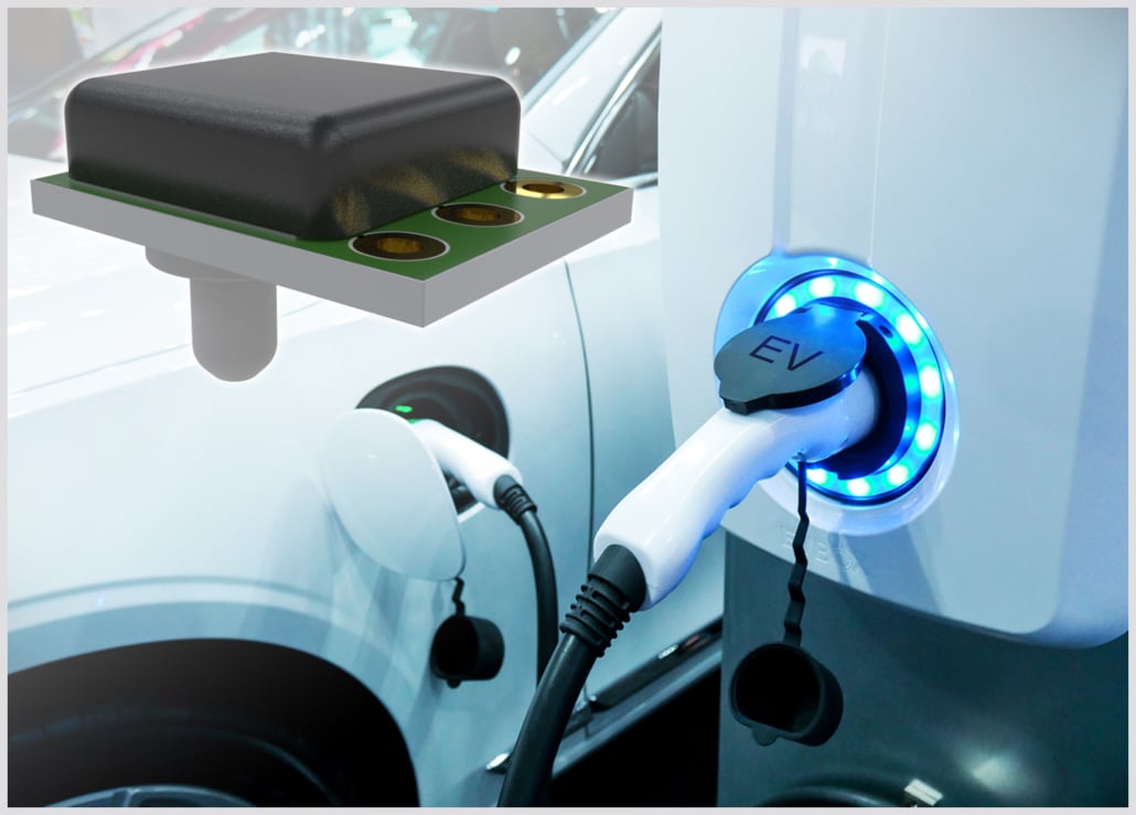
Pressure Sensors and Their Use in Aquatic and Underwater Applications

Pressure sensors are essential safety and logistic equipment in a number of underwater applications. For scuba diving, a reliable depth gauge or diving watch is crucial to estimating diving depth and ensuring safe ascent and descent.

Historically, many dive watches and depth gauges have been analog designs. Digital pressure sensors have several advantages over analog sensors and can be easily interfaced with dive computers that combine information from multiple sensors.

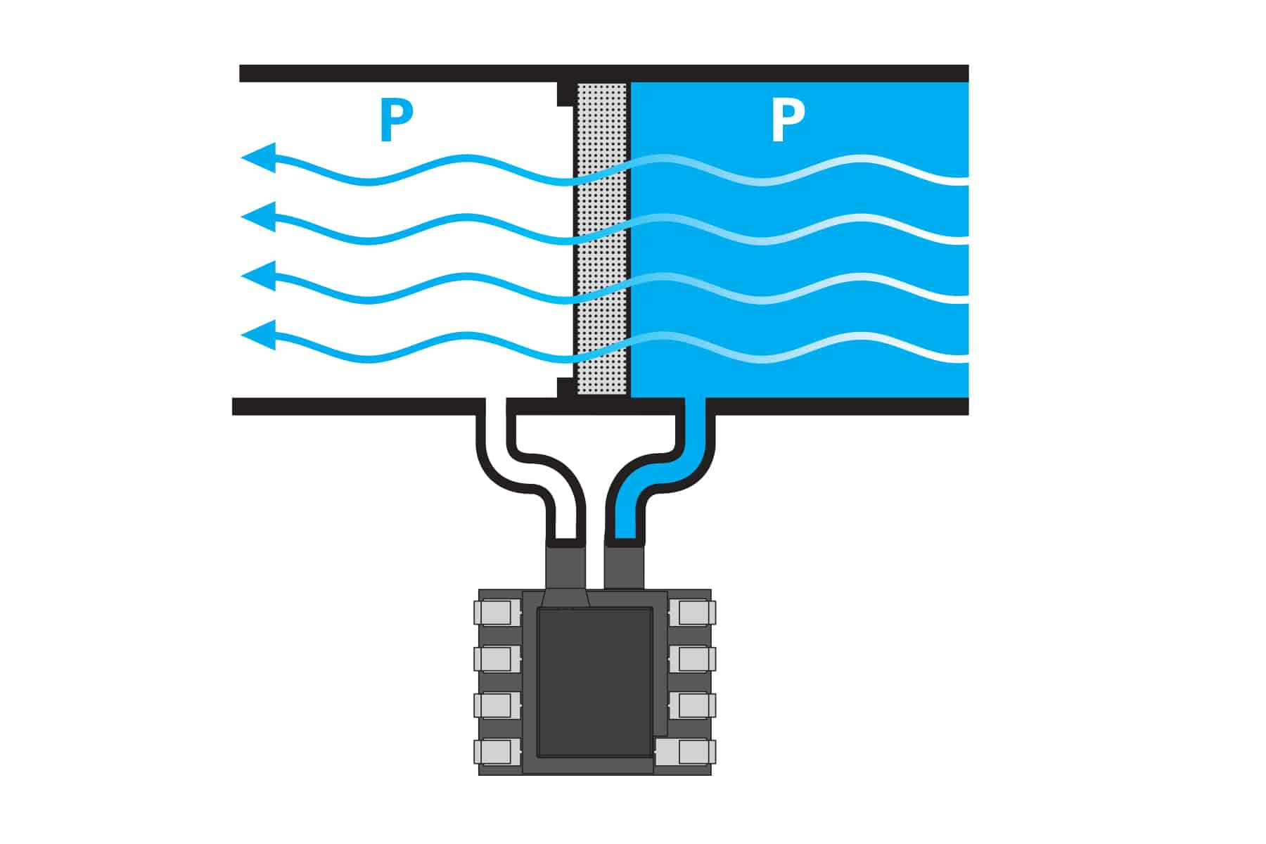
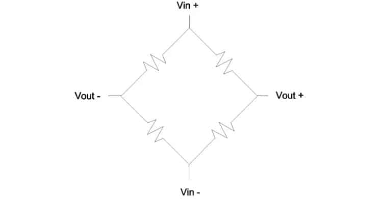
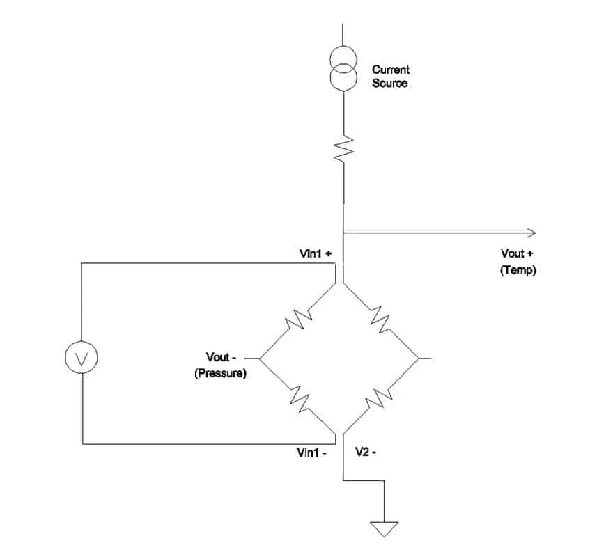
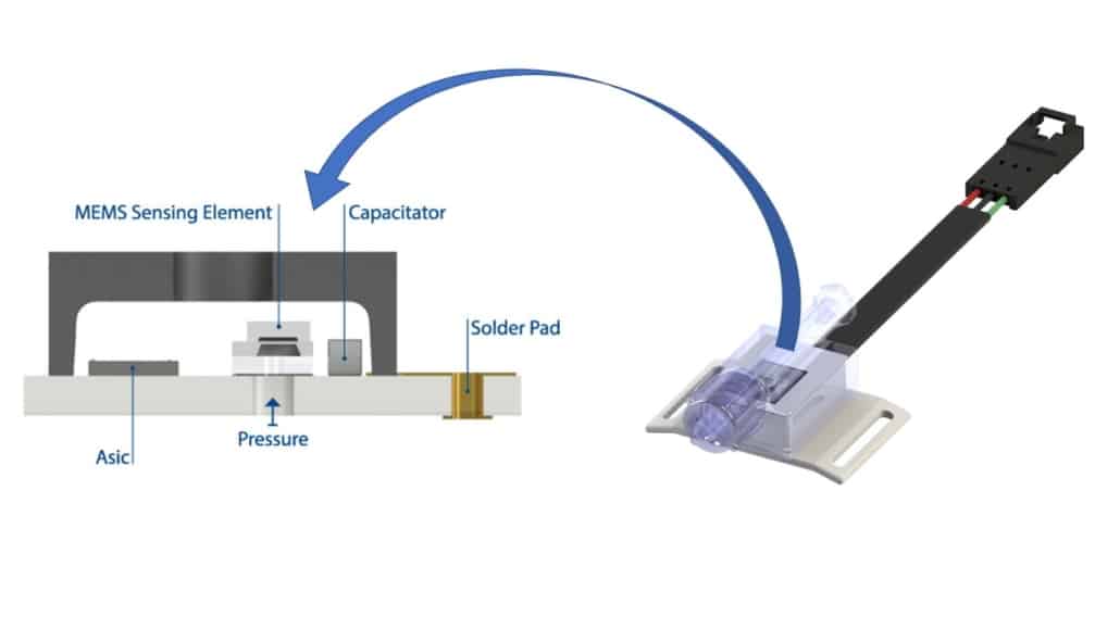
A digital pressure sensor will consist of the sensing element; for pressure sensors, this is often a piezoresistive element and a transducer to convert the sensor response into a digital signal for processing. Digital sensors can be very compact, with no moving parts and can be used in harsh and corrosive environments, including in salt waters. Piezoresistive sensors are particularly well-suited for aquatic measurements as they have few restrictions on their operating depths.1

Common applications of such pressure sensors include sonar buoys, sometimes known as sonobuoys, tank and ocean depth measurements, dive watches and fishing.

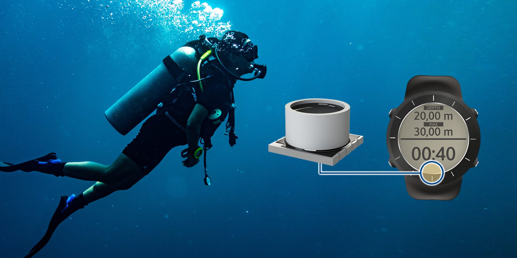
MS Series inside Diving Watch

Merit Sensor Systems

Merit Sensor Systems is a leading expert in pressure sensors for a number of applications, including diving and freshwater work. Merit Sensor Systems offers several different sensing devices with incredibly small footprints and ultra-low power draw. The low power consumption is essential for many remote aquatic applications as devices must be battery operated and require a battery life of many hours.

For sonar buoys, deployable devices that use sonar signals to locate passing submarines and marine traffic or monitor tidal conditions, Merit Sensor Systems has developed pressure sensors that can replace the traditional wire/line technology. Normally, a buoy would be deployed with a spool of wire connecting the device to a float at the surface and the length of the wire is used to estimate the depth of the device. However, as the ocean is constantly moving, the wire displacement is often a bad measure of the depth due to lateral deflections of the device while it is in the water. A pressure sensor can instead provide more accurate depth measurements by measuring the local water pressure.

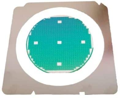
For sonar buoys, Merit Sensor Systems offers a range of suitable sensors, including the HTS 1510 Series, the TR series and, for more limited operating depths, the ultra low power MS series. All of these are highly compact, lightweight sensors that can be easily incorporated into a range of devices and provide many hours of continuous operation. The HTS series will also soon feature a Sleep mode so that the battery life can be further preserved.

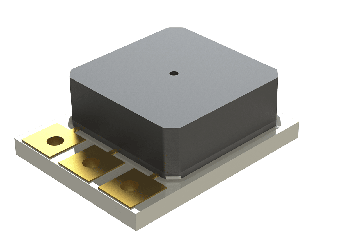
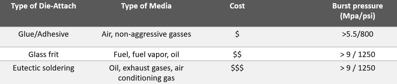
All of the Merit Sensor Systems series are extremely media compatible with a range of water environments and conditions. The MS series is gel-filled for additional protection and its compact design footprint means it has been successfully used in dive watches. The MS series is an affordable option with excellent stability over an extensive temperature range and is also RoHS compliant.

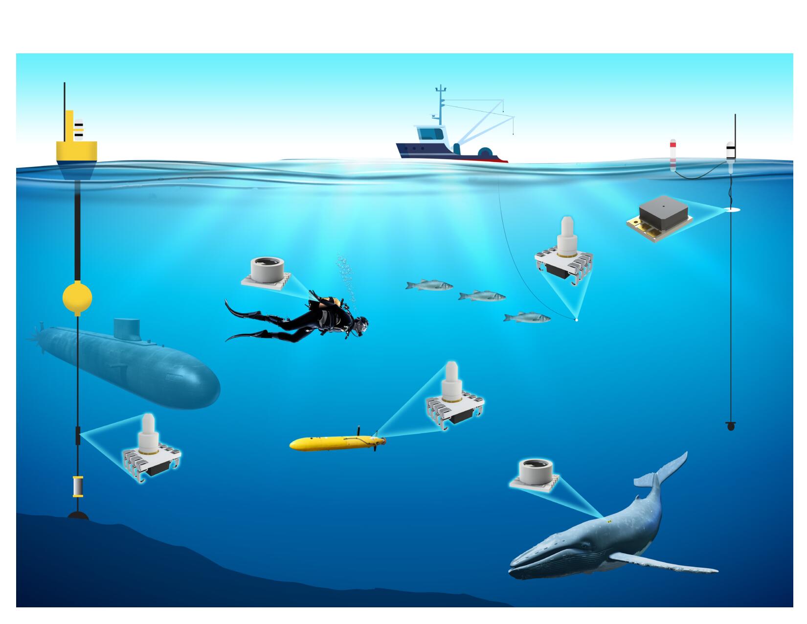
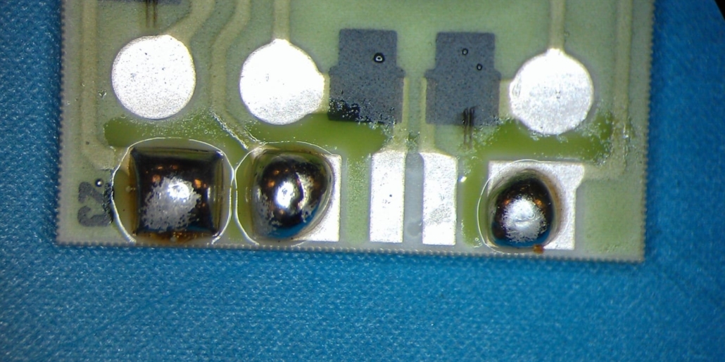
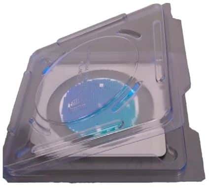
HTS, TR, & MS Series in underwater applications.
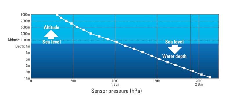
Calculating Depth

Why do pressure sensors work so well for recovering depth information? As the density of water is constant in most environments, as is gravity, the underwater pressure is directly proportional to the submersion depth. With onboard electronics for the processing, a pressure sensor can rapidly convert these pressure readings into a measurement of submersion depth or even the local water level.

Diving computers can display and process a range of pressure information, from remaining gas levels in breathing tanks to diving depth. Some dive computers will use this to calculate the remaining safe time for a dive.

All of the Merit Sensor Systems pressure sensor series can be integrated as part of digital systems, but the HTS 1510 Series has the choice of providing digital or analog outputs.

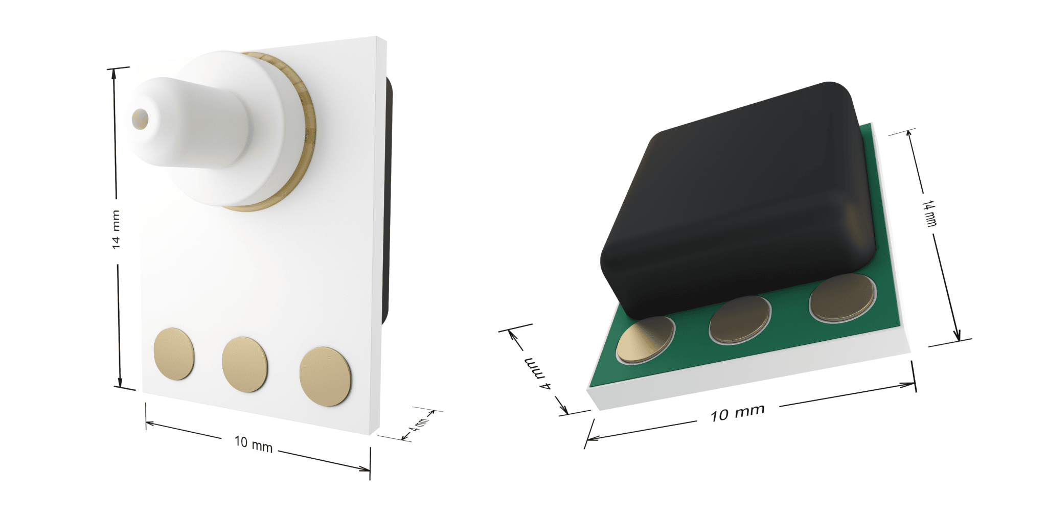
Important for live depth calculations, all of the pressure sensors have 10 ms start up times in case devices need to be rebooted rapidly. Each pressure sensor is less than 2 g in mass, including any protective housing and mounts required, particularly for saltwater applications.

These pressure sensors are characterized by their potential to perform high accuracy measurements with only 0.5 % FS lifetime drifts, incredibly low pressure and temperature hysteresis. Whether you need a pressure sensor that can uphold the highest safety standards for manual diving, or a quick readout sensor for 24/7 online water tank monitoring, Merit Sensor Systems has something to offer.

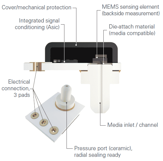
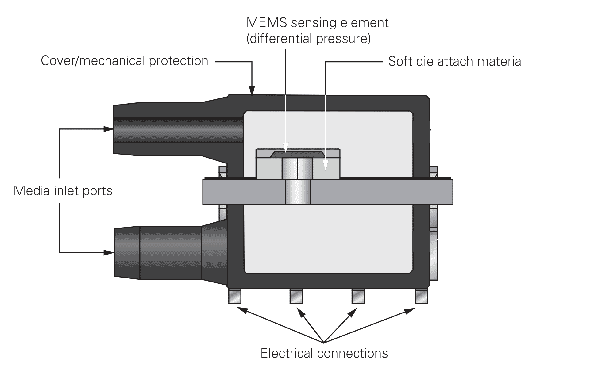
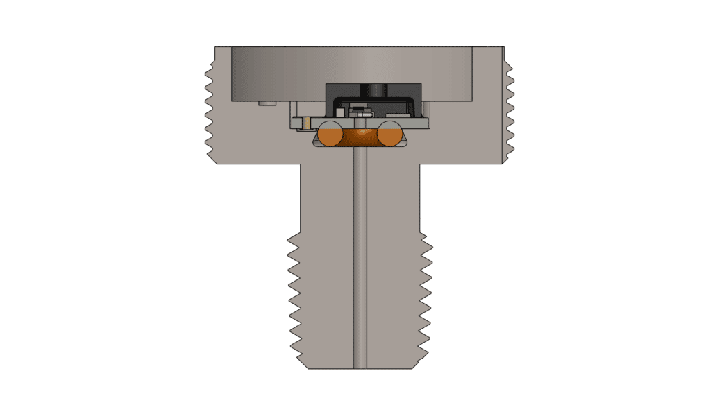
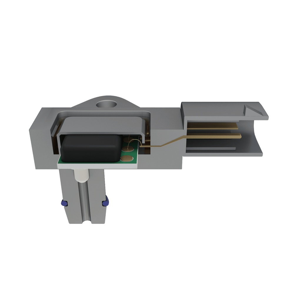
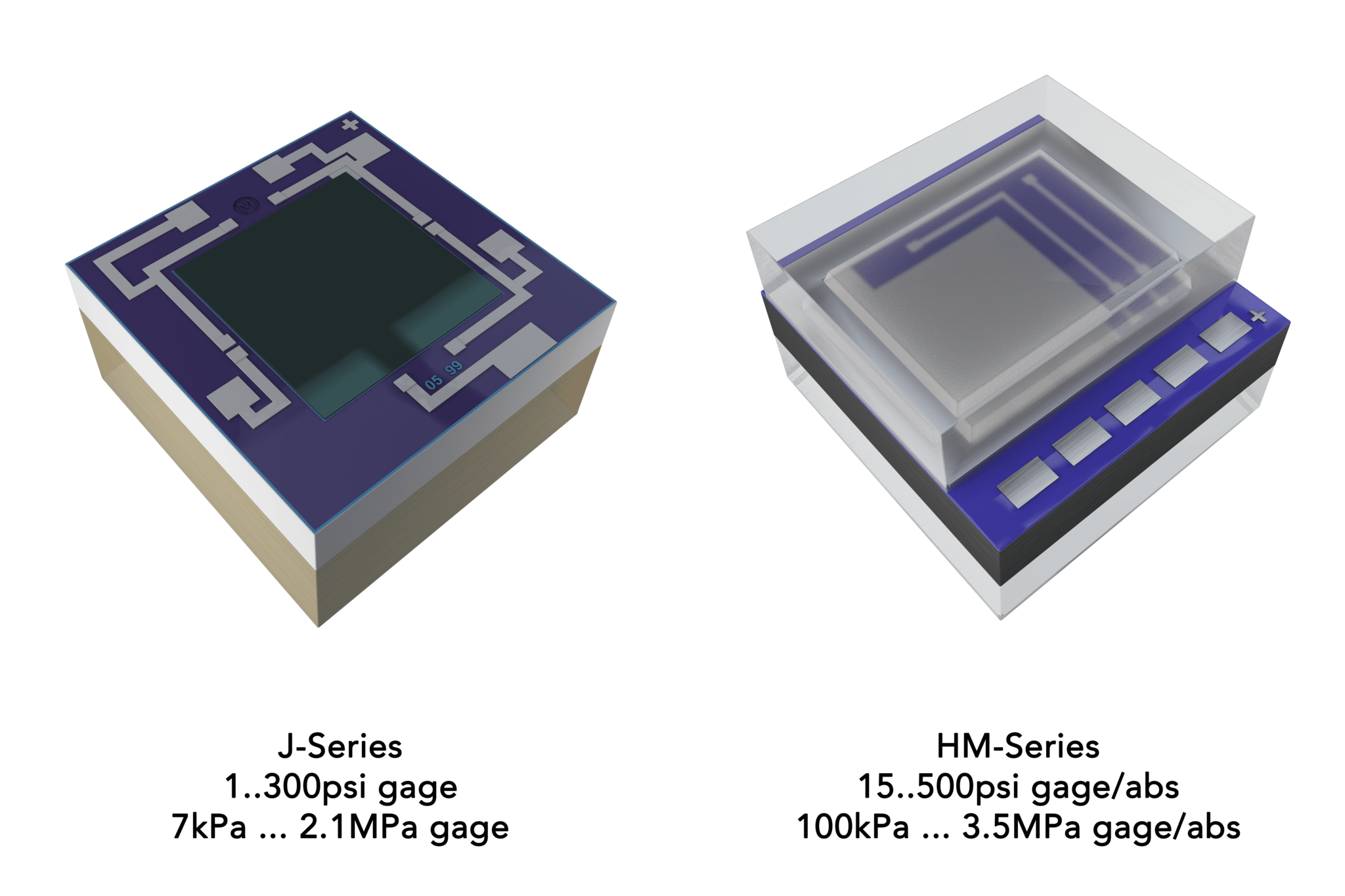
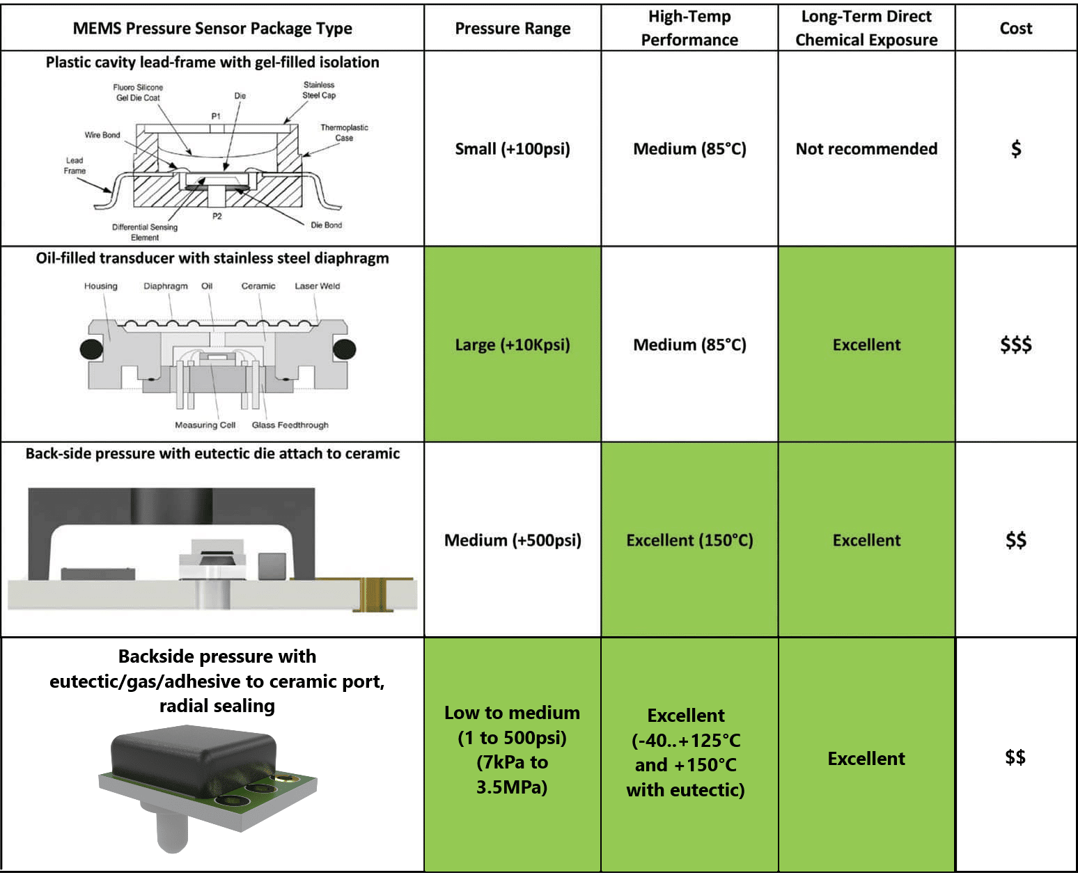
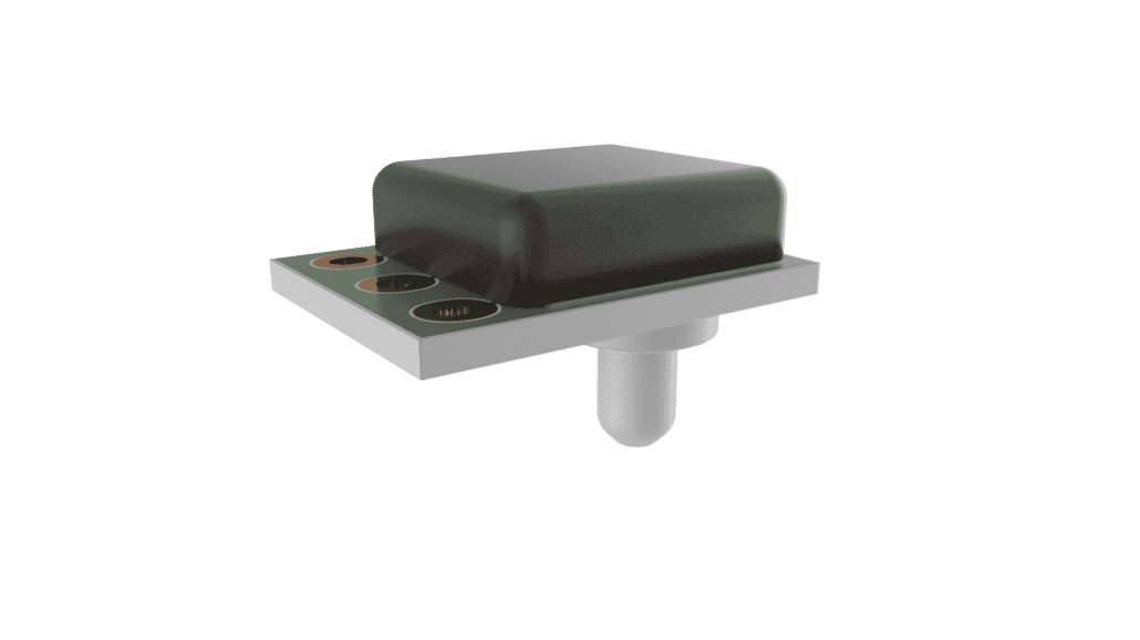
The HTS 1510 Series, the TR series and the MS series each have different designs and housing to optimize them for particular tasks. The MS series is a surface-mounted, ceramic device. The fully-compensated TR series is a direct-media pressure monitor, designed to plug and play with existing devices. The HTS1510 series is a backside-pressure monitor which can be surface-mounted and integrated into existing control boards.

Contact Merit Sensor Systems today to find out how their state-of-the-art pressure sensors could be integrated into your underwater devices.

References:

  1. Büttgenbach, S., Constantinou, I., Dietzel, A., & Leester-Schädel, M. (2020). Case Studies in Micromechatronics. In Case Studies in Micromechatronics. https://doi.org/10.1007/978-3-662-61320-7

For more information visit this article featured on AZOSensors.com

Implementing Pressure Sensors into HVAC Systems

HVAC systems are vital when it comes to ensuring indoor air quality, health, and inhabitant comfort management.HVAC systems also have a central role in enhancing a building’s energy efficiency, as HVAC systems represent almost 50 % of the total energy consumption of buildings in the US and 20 % of all total energy consumption.2

Global temperatures and weather are likely to force an increased reliance on HVAC systems worldwide, meaning increased energy consumption which places utmost importance on finding ways to improve the efficiency of HVAC systems.3

One of the ways to achieve this is by using smart management systems for HVAC to do things like switch off unnecessary heating or ventilation in low or zero-occupancy buildings to ensure that no energy is wasted.4

The use of sensors lies at the core of smart HVAC systems. Sensors facilitate ‘machine vision’ for an automated system, delivering the information required to make intelligent decisions predicated on current demand and specified performance.

Sensors can also be incorporated into HVAC systems to enhance climate control and help send alerts when necessary maintenance to avoid needless work, which may also prevent system downtime.

Pressure Sensors in HVAC

Merit Sensor Systems is a global leader in the design and development of high-performance pressure sensors. Pressure sensors are one of the most important components in HVAC system technology for monitoring system performance, reviewing compressor conditions, and monitoring ducts to test the airflow through the ventilation systems.

Merit Sensor Systems has the services that help clients find the appropriate pressure sensors to make HVAC systems safer, more reliable, and cheaper to run.

HVAC systems are made of several components as a single system will need to have the capacity of cooling, warming, and providing air transport around the system and ventilation.

Continuous real-time pressure monitoring is suitable for checking if rooms or filters have pressure drops across them in order to check occupancy and performance. HVAC pressure sensors can also be installed to preserve pressure levels in key airways or those that necessitate positive pressures for safety reasons, including hospital laboratories.

LP Pressure Sensor

Compression

Conventional HVAC units typically contain a compressor that compresses a refrigerant vapor until it is transformed into a hot gas.

Pressure monitoring is crucial to check for leaks in this refrigerant application and the compressor performance, which is made possible with the TVC Series. Once the hot air is produced, it is cooled with ambient air that is subsequently heated by the transfer.

The gaseous refrigerant is pumped towards an evaporator as it cools, where it flows through a restrictor device to reduce the pressure of the refrigerant and evaporate it, cooling the air for recirculation.

There are various compressor designs, but the majority utilize the compression, evaporation, and cooling cycle to lower the air temperature.

TVC Pressure Sensor

Choosing Pressure Sensors

There are a number of different applications and a significant demand for pressure sensors in HVAC systems, but to be useful, pressure sensors need to have specific performance levels.

Some of the pressure changes in HVAC, including pressure drops across filters as a result of slight clogging, may be very small. Therefore, the pressure sensor needs to have a good limit of detection.

Small pressure changes and small overall pressures can also be observed in ventilation systems that require extremely sensitive pressure sensors. As smart HVAC systems are typically used to reduce energy consumption and waste, the pressure sensors that are installed in the system need to be completely reliable.

Errant and erroneous readings could lead to poor performance in the HVAC system or even damage components if maintenance warnings are not offered at the appropriate times.

The extremely compact LP Series pressure sensor is also part of Merit Sensor Systems’ portfolio and helps address all of these issues.

The LP Series pressure sensor has a low footprint and can be easily integrated into a circuit board design without resulting in extra bulk or weight to the finished product. The small footprint makes integration into nearly any application possible without the need for majorly redesigning components.

LP Pressure Sensor

LP and TVC Series Pressure Sensors

For HVAC applications, the LP Series pressure sensor has a detection capacity down to just 250 Pa with a resolution of more than 0.01 Pa. Initially designed with a sensitivity for the measurement of differential or gauge pressures, this pressure sensor requires just a 3.3- to 3.5 V supply to start supplying accurate and meaningful data.

The LP series pressure sensor contains two connectable (with tubing) pressure points. The sensor can then be connected via I2C or analog output for data monitoring in real-time as well as integration into smart building management systems.

The TVC Series is ideal for measuring refrigerant gas at higher pressures. It was developed to create a stable output, even at temperatures between –40 to 150 °C. The TVC is tasked with monitoring HVAC systems, water levels, water pressure and processes. It can also be used for air-conditioning and other refrigerant systems.

Inside the TVC Pressure Sensor

Inside the LP Pressure Sensor

Contact Merit Sensor Systems today to discover more and discover how the LP and TVC Series can revolutionize the efficiency of HVAC systems, with the sensitivity to determine exactly when the next maintenance cycle is due.

References and Further Reading

  1. Bearg, D. W. (2019). Indoor air quality and HVAC systems. Routledge. https://doi.org/10.1201/9780203751152
  2. Perez-Lombard, L., Ortiz, J., & Pout, C. (2008). A review on buildings energy consumption information ´. Energy and Buildings, 40, 394–398. https://doi.org/10.1016/j.enbuild.2007.03.007
  3. Wang, H., & Chen, Q. (2020). Impact of climate change heating and cooling energy use in buildings in the United States. Energy & Buildings, 82(2014), 428–436. https://doi.org/10.1016/j.enbuild.2014.07.034
  4. Wang, H., & Chen, Q. (2020). Impact of climate change heating and cooling energy use in buildings in the United States. Energy & Buildings, 82(2014), 428–436. https://doi.org/10.1016/j.enbuild.2014.07.034

For more information, visit this article on AZOSensors.com

Electric Vehicle Cooling Systems and the Role of Pressure Sensors

The rise in popularity and uptake of electric vehicles cannot simply be put into words; one has to look at the data. Research carried out by the International Council on Clean Transportation (ICCT) in 2017 determined that global annual electric vehicle sales were increasing nearly at an exponential rate.1

TVC in an Electric Vehicle

By the end of 2020, more than 10 million electric cars were navigating roads across the world.2

Electric Vehicles are appealing to buyers for many reasons: they produce fewer emissions, can be operated at significantly lower costs and offer improved long-term prospects compared to gasoline-fueled cars.3–5

However, one of the greatest challenges in getting more people to convert to electric vehicles has long been the limited range that they can travel on a single charge.6 However, this obstacle is steadily being overcome.

Incremental improvements in battery technology are on the rise, and the maximum range of electric vehicles is extended with each advance, making electric vehicle ownership a more viable option for a future generation of drivers.

The Importance of Cooling Systems in Electric Vehicles

Attempts at improving battery capacity, however, can present certain challenges. The main question is related to cooling. Batteries generate heat when they charge and discharge. Therefore, the more energy a battery stores and the more quickly it charges or discharges, the more heat it will tend to create.

Vehicles that are entirely electric are equipped with a cooling system that maintains particular temperature limits in the vehicle’s power electronics and battery packs. The main role of the cooling system is to ensure that the battery temperature remains within safe operating limits.

If the lithium-ion battery pack’s temperature in any given cell gets too hot, it can provoke a chain reaction known as thermal runaway, in which the complete battery pack experiences catastrophic exothermic decomposition.7

Preventing overheating and thermal runaway is, of course, critical. The majority of EV cooling systems aim to keep battery packs at their optimum operating temperature most of the time.

Usually, this means a close-to-uniform temperature distribution in the 15 – 35 °C range.8 If temperatures are allowed to significantly vary throughout the pack or fall outside this particular range, then charging times and efficiency can be negatively affected resulting in a reduction in the service life of the battery.

EV Cooling Technologies

Electric vehicles employ various cooling technologies to manage the temperature of power systems: air, fins and liquid cooling.

Fin cooling is a simple and economical passive cooling mechanism that has been demonstrated to be successful in the world of electronics.

Effectively, building power-intensive components to feature fins and ridges as opposed to flat faces increases their surface area, thereby improving the rate at which they can dissipate heat to their surroundings.

However, fins have limited application in electric vehicles as they can increase the weight of power systems significantly.

Air cooling, the circulation of relatively cool air across the surface of a hot object, is another comparatively simple technology as it will cool it down more rapidly.

Air cooling is typically cost-effective and has been employed in some electric car models (including early models of the Nissan Leaf). However, this system can be relatively energy-intensive, and cars that are dependent on air cooling can run into trouble in hot weather.8

Liquid cooling is the most efficient way of controlling the temperature of batteries and power systems in electric vehicles.

Piping liquid coolant throughout power systems facilitates effective heat removal and while it is comparatively expensive and complex, it offers more precise temperature control of electronic systems and battery packs in electric vehicles.

As manufacturers are driving towards installing increasingly higher capacity battery packs in electric vehicles, the demands that these cooling systems must be able to cope with are also increasing.

Liquid cooling systems are becoming more crucial and complex as charging rates and battery capacity increase.9,10 Liquid cooling systems in today’s electric vehicles may necessitate subdivision of the cooling system into several circuits and heat exchange between battery coolant and A/C system refrigerant.

The Role of Pressure Sensors in EV Cooling Systems

Pressure is a key parameter in an electric vehicle’s liquid cooling system. Pressure sensors are vital components both for feedback for cooling system regulation and optimization as well as being able to detect pressure loss that could suggest a leak.

As liquid cooling systems grow in complexity, the demand for accurate and robust pressure sensors for EV cooling systems is now greater than any time before.

Merit Sensor Systems designs and manufactures a wide range of high-performance pressure sensors appropriate for demanding EV applications. The TR series sensors have been developed to offer precise pressure measurements in harsh media such as gases, oils and refrigerants.

TR series pressure sensors incorporate a hermetically sealed die that is able to take pressure measurements from the backside, where the media only comes into contact with the ceramic substrate, glass and gold-tin eutectic solder.

TR series sensors also offer accurate, dependable and robust pressure sensing in complex EV fluid system applications while rated for temperatures from -40 °C to 150 °C.

TR-Series face sealing integration (MeriTrek starter Kit) into metal/plastic housing.

TVC series sensors have been optimized for measuring mid-to-high pressures in refrigerant gases up to 2,000 kPa.

Mounting the silicon die sensing element at the top of a ceramic pressure port means the TVC sensors have the capacity to measure backside pressure while separating the media from internal electronics, offering reliable and robust pressure (burst pressure 5x) measurements over a prolonged service life, even in harsh media.

TVC-Series easy integration in metal / plastic housing with radial sealing (o-ring).

With simple sealing and electrical connections, TR and TVC series pressure sensors have been engineered for seamless integration into complex fluid system pipelines and rapid connectors owing to reliable face and radial sealing.

To discover more, contact Merit Sensor Systems and find out how its pressure sensors offer a series of unparalleled advantages in EV systems.

References

  1. Lutsey, N. & Nicholas, M. Update on electric vehicle costs in the United States through 2030. (2019).
  2. Global EV Outlook 2021 – Analysis. IEA https://www.iea.org/reports/global-ev-outlook-2021.
  3. How green are electric cars? | Environment | The Guardian.
  4. Running Costs of EVs: How much it costs to buy and run an electric car | OVO Energy. https://www.ovoenergy.com/guides/energy-guides/how-much-does-it-cost-to-charge-and-run-an-electric-car.htmlhttps://www.ovoenergy.com/guides/energy-guides/how-much-does-it-cost-to-charge-and-run-an-electric-car.html.
  5. How long before we run out of fossil fuels? Our World in Data https://ourworldindata.org/how-long-before-we-run-out-of-fossil-fuels.
  6. The real barriers to electric vehicle adoption. MIT Sloan https://mitsloan.mit.edu/ideas-made-to-matter/real-barriers-to-electric-vehicle-adoption.
  7. Feng, X., Ren, D., He, X. & Ouyang, M. Mitigating Thermal Runaway of Lithium-Ion Batteries. Joule 4, 743–770 (2020).
  8. Chen, D., Jiang, J., Kim, G.-H., Yang, C. & Pesaran, A. Comparison of different cooling methods for lithium ion battery cells. Applied Thermal Engineering 94, 846–854 (2016).
  1. Design of Direct and Indirect Liquid Cooling Systems for High-Capacity, High-Power Lithium-Ion Battery Packs on JSTOR. https://www.jstor.org/stable/26169002.

For more information, visit this article on AZOSensors.com

Why a Pressure Sensor’s Packaging Matters

System developers who require pressure sensing capabilities where the sensor will be exposed to harsh media and extended temperature should know that packaging is critical to improve the pressure sensor’s reliability. Pressure sensors are often exposed to harsh fluids, such as gas, oil, refrigerant, and other caustic solvents that can damage the sensor’s circuitry if the sensor is not properly packaged. Damaged pressure sensors can lead to sensing errors and ultimately product recalls and safety risks.

Aerospace and automotive specifications are particularly stringent. In these applications temperatures range between -40 and 150 °C. Furthermore, accuracy and reliability requirements in these applications tend to be demanding, as a component failure can result in safety risk and/or product recall.

Another thing to consider that is related to temperature is the thermal coefficients of expansion (TCE) between the MEMS sensing element, or die, and the substrate on which it is attached. Stainless steel might seem like a great substrate material, but its TCE is much higher than the TCE of silicon, of which the MEMS die is made. In short, the stainless steel expands and contracts much more than does the silicon. These differences in TCE cause the MEMS sensing element to react as it would with real pressure, therefore introducing sensing errors.

TR Series for a face seal and backside pressure

The media also has to be considered. Adhesives are often used to seal the MEMS die to the substrate and protect the sensor’s circuitry. However, adhesives do soften with extended exposure to harsh media. Medical applications, for example, do not expose the sensor to media as harsh as gasoline, but even saline can be corrosive after the sensor is exposed to it long enough. Furthermore, the cleaning and sterilization process typically requires repeated contact with caustic chemicals, such as bleach. When the adhesives soften and seals break, the circuitry can be damaged, and sensing errors can occur.

In addition to temperature and media, pressure must be considered. High enough pressures—around 300 psi—can cause the MEMS sensing element to detach from the substrate when adhesives are used for the MEMS die bond.

Another thing that degrades the bond strength of adhesives is humidity. Very few adhesives or epoxies can withstand long-term exposure to elevated temperatures with high humidity. And the specialty epoxies designed for this environment will exert a significant stress on the MEMS sensing element, again triggering sensing errors.

For a pressure sensor to perform well from -40 to 150 °C, even in harsh media and pressure above 300 psi, the right packaging is essential.

TR Series for an O-ring seal and backside pressure

We at Merit Sensor have ensured that our pressure sensors have been designed for harsh media and high temperature. We have innovative die bonds made of elements that are very resilient to harsh media. These die bonds are done on ceramic substrates, resulting in closely matched TCEs. This results in pressure sensor packages with high accuracy and reliability.

For more information, visit this article featured on AZOSensors.com

Pressure Sensor Platform for a Range of Harsh-Environments

A compact MEMS device with integrated signal conditioning is needed by many pressure sensor applications; however, the challenge is to find an approach that is capable of supporting the application’s volume and cost requirements including flexibility in terms of pressure range. From industrial to medical applications, after-market to OEM automotive high-volume projects, the solution is considered to be a platform that can be adapted based on the pressure range, temperature range and media compatibility.

The Merit Sensor TVC sensing platform is a new approach that addresses applications that need lower pressure ranges integrated with a radial seal. Instead of a single-chip solution, which limits pressure range and output configuration changes, these applications are perfectly suited to a customizable sensor platform that incorporates the MEMS device and signal conditioning in a compact, cost-effective package.

Sensor Platform Meets Exact Application Needs

The customizable sensor platform incorporates a high-sensitivity MEMS device chosen from one of the globally leading, largest MEMS sensing element portfolios, which comprises of devices from the lowest range of 7 kPa up to 3.5 MPa absolute, along with an individual signal conditioning capability. This supports almost any application with readily available components, saving the investment in the production of a device for particular dimensions and ranges. The signal conditioning ASIC with the related electronics components is fixed on a harsh-media-compatible ceramic substrate. The MEMS sensor is fixed on a pre-molded, ferrule-type ceramic pressure port, thus preventing any additional potential leak paths.

The MEMS backside, the ceramic port and the attach material are the only elements exposed to the media. The populated ceramic substrate completely protects the components, and hence does not require the addition of dedicated media-compatible coatings. The components and the signal conditioning fulfill EMI/ESD protection norms, thus the all-in-one sensor platform minimizes the requirement for external components.

The two-component solution includes both signal conditioning and MEMS in separate mechanically attached subgroups. This enables Merit Sensor to choose both the exact MEMS pressure sensor and signal conditioning output (analog or SENT) required for the end user application. Keeping the two elements separated has a functional advantage and also provides a more cost-efficient solution by taking advantage of higher quantity MEMS unit cost, even if the signal conditioning needs change across applications.

The MEMS sensing element is considered to be a key component for the platform. The TVC-Series can cover from 7 kPa to 3.5 MPa pressure applications along with the HM and J-Series. Both series have been designed for backside pressure measurements, and the HM-Series (harsh environment MEMS) covers the absolute configuration from 100 kPa to 3.5 MPa as well. The J-Series is the most sensitive element (5333 µV/V/ psi = 760 µV/V/kPa), employed as gage configuration (backside) and comprising of superior pressure (< 0.025% FS) and thermal hysteresis (< 0.1% FS) in order to deliver a stable signal to the signal conditioning via wide temperature ranges and low pressure.

Merit Sensor knowhow is applied to the MEMS geometry and configuration, mainly on the glass thickness, in order to ensure the correct mechanical decoupling for optimal thermal behavior and stability. The three die-attach processes provided within the platform address varied application requirements, thus combining the best MEMS thermal behavior with burst pressure along with the requested media compatibility. MEMS sensing elements are developed by Merit Sensor’s own fab, which provides direct and dynamic control of the different solutions.

Figure 1. The Merit Sensor TVC sensing module is highly customizable to meet specific application requirements in a cost-efficient, compact package.

Figure 2. Pressure sensing elements can be chosen from the world’s largest portfolio of MEMS pressure sensor devices.

Choose Appropriate Attach Process for Environment and Cost

The sensing platform is geometrically compact, and the cavity and pressure port have defined dimensions for air, fluids and gas. However, a vital element for accuracy and reliability is the choice of die-attach. Conventional adhesives that are used for creating the pressure seal and protecting the sensor die and related circuitry are considered to be a cost-effective approach for non-aggressive gases and air, but they eventually soften in harsh vapors or fluids. Once the seal breaks, the sensor circuitry is damaged, developing a common reliability failure that can be expensive if it leads to a product recall or demands regular maintenance and replacement of the sensing subsystem.

At the other end of the spectrum, a eutectic die bond using a gold-tin soldering alloy provides a hermetic seal even in harsh fluids, at extremely wide temperature ranges and at high pressure. While this gold-tin solder is a lot more expensive than adhesive, the cost difference is minute in comparison to the major improvement in prolonged reliability and maintenance costs.

The die-attach process using the glass-frit introduced with the TVC platform is considered to be a cost-efficient solution for high-burst pressure in terms of reliability, improved media-resistance compared to adhesive and more stability in medium/low pressure ranges thanks to the close-to-silicon TCE sealing material. The high temperature (> 300 °C) curing process during the MEMS-to-port assembly guarantees stability in wide temperature range applications.

Merit Sensor offers a wide range of MEMS attach processes on the Al2O3 ceramic pressure port in order to support sensor media and environment demands, and also cost and reliability requirements of each application (see Table 1). The MEMS backside pressure measurement, along with the dedicated die-attach process of the platform, ensures a safe burst pressure in every pressure range (Table 1).

Table 1. Comparison of die-attach approaches and appropriate media, along with trade-offs in cost and burst pressure.

Customizable Pressure Sensing Platform Addresses Full Range of Design Decisions

The Merit Sensor TVC sensing module addresses a variety of application-oriented requirements with a single solution. This covers the low-pressure, below 100 kPa exhaust gas measurement, up to 3.5 MPa air conditioning gas measurement in just the automotive domain. Both need a solid media compatibility, which involves in-depth knowledge in the MEMS die-attach, as well as matching the accurate components for application temperature and various other environmental requirements.

The sealing joint and choice of how to mechanically incorporate and electrically couple the sensor is majorly dependent on the type of application, pressure range and temperature. Standard electrical connection can be accomplished with lead-frames and pins or with pads without holes (see Figure 3 for example). Thick wire bonding can be used as a mechanical stress-free connection ideal for extremely large temperature ranges from -40 °C to +150 °C and low pressure. The sealing also needs attention to the material (media compatible) and tolerances (leak), as well as determining the pressure range without or with a vacuum, which would need the sensor to be fixed in order to avoid any movement by negative/positive pressure crossing.


Figure 3. 3D view of the TVC Merit Sensor compact module, 3D step file is available for a quick design-in into the end sensor housing.

The pressure port configuration, permitting the radial sealing and limiting the material in contact with the media (simplifying the design), expands and then fulfills the Merit Sensor packaged sensing modules solutions. The mechanical stress-free design enables the use of very sensitive MEMS elements, ideally supporting the low pressure needed for the most challenging applications that are currently available, and these include fuel vapor, exhaust gas and fuel pressure. The 14 x 10 x 4 mm compact geometry sensing module includes all essential components.

Comparison of sensor package type and design considerations.

The use of the modern ASIC to support analog or SENT output allows the setup and calibration from the three external pads, which indeed supports data programming (traceability) and customization (output values, parameters), even when the sensing module has previously been installed in the housing. The TVC-Series is supplied as temperature-and pressure-calibrated, attaining accuracy better than 2.5 %FS between -40 °C to+125 °C. The accuracy can vary based on the pressure range and MEMS attach technology.

Merit Sensor is completing the portfolio for high temperature, harsh environment applications with a solution that is capable of solving the mechanical stress and expands to the low pressure incorporating new MEMS (J-Series) and attach technology, for a cost-efficient solution.

Features

  • Customizable
  • Compact design
  • Limited requirements for external components
  • Wide range of pressures (7 kPa…3.5 MPa)
  • Reduced mechanical influence (housing integration)
  • All-in-one, ready-to-use sensing module (tested, calibrated)
  • Cost-efficient solution for media-compatible applications

For more information, visit this article on AZOSensors.com

An Introduction to Reflow Soldering and Soldering Methods

The objective of this article is to explain the best techniques for soldering sensors manufactured by Merit Sensor using automated equipment. All profiles must be assessed and tested for best performance.

Due to concerns over the safety of lead and new regulations prohibiting its use, such as the Restriction on Hazardous Substances (RoHS) Directive in Europe, an increasing number of companies have stopped using conventional tin-lead (Sn/Pb) solder in the manufacture of circuit boards. The RoHS Directive has banned the European sale of new electrical and electronic equipment containing more than the specified levels of cadmium, hexavalent chromium, lead, mercury, polybrominated biphenyl (PBB), and polybrominated diphenyl ether (PBDE) flame retardants.

Merit Sensor provides pressure sensors that are fixed on ceramic substrates and are RoHS compliant. The lead-free solder pads are plated with AgPt to assure an excellent solder joint for most PCB connections.

Merit Sensor parts can be soldered using either Pb-containing or Pb-free solder process. The aim of this article is to guide customers on how to solder Merit Sensor parts using either Pb-free solder or Pb-containing solder.

In order to meet the RoHS directive, products must be soldered with Pb-free solder.

Soldering with Pb-Free Solder

As the pressure sensors from Merit Sensor are fabricated on ceramic, a Pb-free solder should be chosen that is well-suited with the solder pads. Merit Sensor suggests using solder alloys with SnAgCu that have a melting point of 217-221 °C. Table 1 shows the Pb-free solder alloys in the SnAgCu family.

Table 1. Pb-free solder alloys of the SnAgCu family

The surface of Pb-free solder alloys can appear significantly different when compared to Pb-containing solder (See Figure 1). Additionally, when compared to a Pb-containing solder joint, a Pb-free solder joint will have a dull or matte finish. This is because the surface of the solder joint will become rough when Pb-free alloys begin to cool. This roughness is attributed to the increased volume contraction of the Pb-free alloys. Compared to the Pb-containing solder joints, the Pb-free solder joints are often smaller but this would have no effect on the reliability as these are simply cosmetic characteristics.

Figure 1. Examples of a Pb-containing solder joint (left) and a typical finished surface of a Pb-free solder joint (right).

A reflow soldering profile for Pb-free soldering demands a higher melting point when compared to Pb-containing solders. The temperature differences on the board should be reduced because the process time for Pb-free solder is less than Pb-containing solder. Due to this fact, Merit Sensor does not recommend IR Reflow systems for Pb-free soldering, and instead suggests using forced convection reflow systems to ensure a successful Pb-free reflow soldering.

The pressure sensors offered by Merit Sensor can be soldered with profiles that are based on the standard IPC/JEDEC J-STD-020C (January 2004). For identifying the best temperature profile, each process must be assessed. The best temperature profile is defined by the board and the solder paste used.

The recommended profile according to IPC/JEDEC J-STD-020C is shown in Table 2 and Figure 2.

Table 2. Pb-free classification reflow profile according to IPC/JEDEC J-STD-020 C

Figure 2. Pb-free Classification reflow profile according to IPC/JEDEC J-STD-020.

Use of nitrogen — It may be essential to work in nitrogen if air leads to unsatisfactory solder joints due to increased temperature and oxidation of Pb-free solder; however, the majority of Pb-free solder pastes can be used in air. Nitrogen may be used if the solder joints do not have adequate wetting.

Hand Soldering — Merit Sensor does not recommend hand soldering. An excess amount of energy is required for Pb-free soldering when compared to Pb-containing solder alloys. The heat transfer to the solder joint is critical and should never be tried with a soldering iron.

When using a soldering iron, it should be remembered that Pb-free soldering needs a rapid heat transfer to attain a successful solder joint. It may need an increased tip temperature to 360-390 °C and/or a longer period. Use of solder stations of at least 80 watts of power is highly recommended. Pre-heating can be used to decrease the amount of heat caused on the surrounding components during hand soldering, as is done with reflow soldering.

Soldering Pressure Sensors with Pb-Containing Solder

Temperatures should not go beyond 225 °C for 30 seconds if Pb-containing solder is employed. Merit pressure sensors should be soldered with “no-clean” type solder paste which contains 62%Sn36%Pb2%Ag and has a melting point of 179 °C. The solder paste containing 2%Ag significantly reduces the migration of silver from the AgPt pad into the solder paste. Conversely, it is not advisable to use 63%Sn37%Pb solder paste. Table 3 and Figure 3 show the proper reflow profile for SnPb solder.

Table 3. SnPb classification reflow profile according to IPC/JEDEC J-STD-020C

SnPb Classification reflow profile according to IPC.EDEC J-STD-020C.

If the reflow process is followed correctly, then the solder joint should be able to cover the whole solder pad of the ceramic PCB (See Figure 4–left). In most cases, manual soldering will lead to overheating of the device because of the ceramic’s high thermal conductivity. Very low temperatures will lead to partial soldering, that will further lead to a weak connection to the PCB as can be observed in Figure 4 (middle and right). The solder joint in the middle is an example of an adequate solder. However, that solder failed to wet out and cover the whole pad. The joint on the right was exposed to low heat and inadequate solder, which resulted in unsatisfactory pad coverage and also a weak joint as the solder balled up. It is advised to attach a thermocouple to the sensor to optimize the solder profile and ensure that none of the maximum temperatures are surpassed.

Figure 4. Example of good solder joint (left) and bad solder joints (middle and right).

Stress Normalization Delay for Calibration

For best results, Merit Sensor recommends that any surface mount pressure sensor be allowed to rest at room temperature for at least 48 hours prior to calibration. The stress induced by reflow soldering will usually normalize within this period and help improve product calibration.

For more information, visit this article on AZONetwork.com

The Value of Calibration for MEMS Pressure Sensors

Sensors play a huge role in kidney dialysis systems. Image Credit: Aleksandr Ivasenko/Shutterstock.com

The value of a measurement tool is dependent on its accuracy. Measurement devices, like sensors, are found everywhere in automotive, healthcare and industrial settings. For a lot of these applications, it is necessary that the sensors are accurate to ensure quality control and guarantee patient safety.

On the other hand, for Piezoresistive Pressure Sensors, this is a popular choice because of their quick responses, ruggedness, and large range measurements, the changes in temperature influence the pressure output and, eventually, the accuracy. But as long as the dye in a wafer has uniformity, errors that are related with temperature can be corrected, or rewarded.

Pressure-sensor compensation has two popular methods: passive and active. Passive compensation is completed by trimming the resistors while it is being manufactured. It is suitable for environments where the sensor will go through small changes in temperature.  For temperature changes that are more challenging, active compensation utilizes an on-board circuit, or a microcontroller.

This is where the temperature of the pressure sensor’s immediate surroundings is regularly measured by the temperature sensor. It then moves it to the on-board circuit to correct any errors that are temperature-related also known as offset.  This also allows near-zero temperature errors and greater operating ranges, making it an engaging quality for high-quality pressure sensors.

Calibrate It Yourself or Buy It Calibrated

Sensor calibration has two possible options: 1) the sensors in the manufacturing line is calibrated by the pressure-sensor customer or 2) the pressure-sensor manufacturer’s fully compensated; pre-calibrated sensor is integrated by the customer.

There are a few good reasons why pressure-sensor customers might want to calibrate their own sensors.  One reason is that they might already have a microcontroller in their final product, for example, on a board-mountable part.  In situations like this, the active calibration can be completed with the microcontroller.

A customer might also have a sensor-packaging/housing process that puts a large amount of stress on the sensor. When this happens, the pressure sensor that is already calibrated would register additional pressure through the stress-inducing packaging process. The increased pressure would then introduce a new zero point.

One drawback of customers doing their own calibration is that in-line calibration can be difficult to perform and it can be highly disruptive too. Another issue is that purchasing an already-calibrated sensor would cost less than to acquire in-line calibration that would require specialized equipment and expertise.

Most important of all the drawbacks is the time the calibration would require if the customers were to do it on their own. Mass calibration cannot be done as each sensor requires individual calibration. In addition, the temperature range required for calibration means that the equipment takes a long time to reach the required temperature extremes.

Purchasing a fully compensated pressure sensor from a manufacturer, like Merit Sensor, will be more expensive compared to an uncompensated sensor. It is important to weigh this, however, against how much it would cost if the parts are calibrated in house. Time is money.

Purchasing fully compensated parts from the manufacturer is a way to reduce some of the time and costs associated with calibration issues because calibrated parts can simply be plugged in line as required.

This is ideal for companies who want to move products through production faster, particularly those who don’t have the equipment, skill, and process flow to hold in-line calibration. It often makes sense for the pressure-sensor manufacturer that has its own calibration professional, tools, and expertise to do the calibration.

Custom Sensing Solutions

The LP series is one of the various ranges of pressure sensors offered by Merit Sensor for ultra-low-pressure applications. This type of sensor is ideal for applications such as Continuous Positive Airway Pressure (CPAP) machines because of its suitability for use with non-corrosive gases. The LP series offers a pre-calibrated option which means that the pressure sensor is instantly accessible for medical use. It is also suitable for industrial use, in air-filtration systems and spirometry measurements in healthcare.

Merit Sensor offer the PMD series for applications that need low to medium pressures. The PMD series is suitable for use with air and other non-corrosive liquids. It is also capable of measuring differential, absolute, and vacuum pressure. This series is the most ideal pressure sensor for ink level monitoring in printers and can work over 0.34 to 3.5 bar pressure range.  For this application, the calibration is fast and straightforward because it uses an external microprocessor. This means that the uncompensated PMD series is really a popular option.

The TVC series, on the other hand, is suitable with harsh media operations such as high-temperature oil.  The sensor is an excellent choice for the automotive industry because of its high level of media resistance. The device’s radial sealing means it can be integrated at a module level with a minimal introduction of stress.

TVC Series fully compensated pressure sensor

TVC Series

Fully compensated sensors are widely preferred in automotive applications for the reason that they save automotive manufacturers from integrating calibrations that are time-consuming, over a wide temperature range, into their production processes.

For the past 25 years, Merit Sensor has gained so much experience specializing in Piezoresistive Pressure Sensors. It is a very good choice for customers who need pressure sensors for their applications. It offers standard and custom solutions for a wide selection of applications. Merit Sensor can also supply components that are either uncompensated, passively compensated, for use over a narrow temperature range, or fully compensate, for use over a wide temperature range.

Merit Sensor can help if the customers are not sure which solution is the most appropriate to use. All of Merit Sensor’s products come with on time, personal, and trained support in order to find flexible and innovative solutions to get customers’ products to market.

For more information, visit this article on AZOSensors.com

Mounting and Handling of Pressure Die

This article is aimed to describe the best methods for handling and mounting bare die pressure sensors. Merit Sensor manufactures all pressure chips on 4 inch wafers, which are sawn and delivered on Mylar film (foil tape). This foil tape is fixed to a metal wafer frame that is appropriate for the majority of automated die bonders (see Figure 1). If a unit is marked with a black ink dot, it is considered to be a bad unit.

figure 1.

Packaging & Storage

All wafers assembled on foil tape will be supplied in plastic clam shells (see Figure 2), which are subsequently inserted into an antistatic zip-lock bag. It is required that the bags be opened in clean rooms only and stored in a dark, nitrogen-filled cabinet as soon as it is opened. Wafers can be shipped either individually or multiple clamshells in a single plastic antistatic zip-lock bag. The label on each clamshell will include the quantity of good die, purchase order number (if applicable), the part number, and lot and wafer number (see Figure 3). The foil tape will also have the lot and wafer number written on it.

Figure 2.

Figure 3

Storage Temperature is 19-26 °C: In a proper storage environment, the storage time of sawn wafers is about five years. Storage beyond this limit, or storage in a different or uncontrolled environment, may lead to picking problems at die bonding (sticking die) or unreliable wire bonds owing to corrosion of the aluminum bonding pads.

Handling of Wafers

All sensor chips are 100% electrically tested to guarantee that they conform to the datasheet limits. The wafers are visually examined to ensure that all sensors are completely defect-free. The pressure chips are RoHS compliant, and in the majority of cases, consist of a silicon/ glass stack that is electro statically bonded together.

  • All wafers are mounted, tested, diced, and delivered on a metal wafer frame. Depending on the product, each wafer yields about 600 to 1600 pieces.
  • Special care should be taken when handling the wafer as its surface is highly sensitive.
  • Although cleaning is not required, the wafer should be opened in a clean room.
  • It is not recommended to pick the die off the wafer frame with tweezers. The pressure chips should be picked up with a tool made of soft rubber with a vacuum hole in the middle that is bigger than the sensor membrane.
  • The bonding force should not exceed 100 grams in order to prevent mechanical stress, which can lead to an unstable, drifting offset.
  • It is essential to clean all the tools thoroughly to prevent any residue on the bonding pads, which could lead to reliability problems.
  • For gage pressure sensors (hole on backside), ejector pins with 3 or 4 needles may be used to remove the die from the wafer tape.
  • For absolute pressure sensors (no hole on backside) a single ejector needle will be adequate.
  • Process temperatures greater than 225 °C should be avoided. If the maximum temperature is lower, the sensor will be more stable in a long-term.

Mounting of Pressure Chips

  • Die bonding with hard silicone or epoxy will generally result in an unstable offset value and high TCO (temperature coefficient offset).
  • The pressure chips are sensitive to mechanical stress, particularly sensors with full scale pressures below 1 bar. These pressure chips should be mounted using a soft silicone adhesive with a low hardness (A25 or lower) and a bond-line thickness of 50-100 µm. Particularly, care should be taken to prevent the adhesive from climbing up the inside or outside walls of the sensor die as this could lead to unstable output.
  • All pressure chips have been optimized for long-term stability and the highest output signal. In order to achieve the best performance (temperature behavior, long-term drift, hysteresis), special care must be taken when mounting the die.

Attaching the Pressure Chips

  • The bond pads on each pressure chip are at least 100×100 µm. The pad material is made of aluminum and has a thickness of 1-2 µm.
  • An aluminum or gold wire can be used for wire bonding. A good thermo-sonic gold-ball bond, with 30 µm gold wire, will result in a ball shear force of >30 grams and a Pull Force of >6 grams.
  • A soft ion free silicone gel with a viscosity of <1000 cps and no hardness should be used to protect the wire bonds. The gel can have a considerable impact on the sensor performance; hence, special care should be taken when making a selection. Merit Sensor has tested and currently uses Dow Corning Sylgard 527.
  • The gel can be applied as drop on the sensor’s surface to simply protect the bond pads from corrosion. If additional humidity protection is necessary, then the entire area around the sensor including bonding wires can be covered.
  • For gage pressure sensor, where the pressure is applied from the backside, Merit Sensor still recommends to protect the topside of the sensor with a gel to avoid corrosion of the aluminum bonding pad.

For more information, visit this article on AZOSensors.com

Bridge Configurations for Pressure Sensors

This article describes bridge configurations of different pressure sensors, when each can and cannot be used, and the pros and cons of each.

Introduction

Wheatstone bridge is the core of Merit Sensor’s pressure sensors and is comprised of a group of four resistors on a silicon etched diaphragm. When pressure is applied to the diaphragm, the resistors are stressed which changes their resistance.

In an ideal setting, all of the resistors would be perfectly matched and fully independent of temperature.

However, practically, differences exist between the resistance values of each resistor. Moreover, temperature also changes resistor values. The change to resistor values and the overall bridge output caused by temperature is called the Temperature Coefficient of Resistance, or TCR.

A pressure sensor operating independently of temperature is needed in many applications. Such applications require the compensation of the pressure sensor’s TCR.

TCR compensation can be done in two general methods – passive and active. In passive compensation, values of each bridge resistor must be measured in order to determine the values required for the compensation resistors.

In active compensation, an analog circuit, a microcontroller, or signal conditioner records the bridge output across various pressure and temperature conditions and adjusts sensor outputs accordingly.

Bridge Configurations

a. Closed – A bridge in which all resistors are connected (See Figure 1).

Figure 1. Closed bridge.

In a closed bridge, individual resistors cannot be measured because the other three resistors of the bridge will always have an influence over them.

b. Half Open – A half open bridge is divided into two branches and connected at one end (See Figure 2).

Figure 2. Half open bridge.

Unlike closed bridge, a half open bridge allows for each resistor to be measured, which is an advantage if the performance of the sensor needs to be determined. In addition, a half open bridge enables the addition of either active or passive compensation as required.

An additional electrical connection is needed by a half open bridge.

c. Full Open – A full open bridge is divided into two branches, and is open at both ends (See Figure 3).

Figure 3. Full open bridge.

Just as half open bridge, the full open bridge also enables the measurement for each resistor. It can use either active or passive compensation. Additionally, each half of the bridge can be powered and measured independently which is an advantage because some signal conditioners commonly used in pressure sensor applications require two independent branches.

However, the full open bridge configuration needs an additional electrical connection which is beyond that required by the half open configuration.

Examples of Implementations

a. Closed – As it is not possible to measure the individual resistors in a closed bridge, it can be used with active compensation or in an application where sensor output fluctuations caused by temperature changes are acceptable.

A closed bridge with active compensation is shown in Figure 4.

Figure 4. Closed Bridge with Interface device (Signal Conditioning ASIC, Microcontroller, Analog circuitry, Etc.)

A pressure switch is one example of a suitable application for a closed bridge, where temperature independence is not critical. Here, knowing that a pressure threshold has been reached is more important than measuring the absolute pressure.

b. Half Open – As shown in Figure 4, active compensation can be applied to the half open bridge. Similarly, passive compensation can also be applied to the half open bridge as shown in Figure 5.

Figure 5. Half open bridge with passive compensation.

Figure 5 shows the implementation of a half open bridge with passive compensation, indicating that added components and the extra electrical connection (Vin+) are needed to close the bridge. Just as the name conveys, additional resistors accomplish span, zero and output impedance compensation. These components have to be added after taking the open bridge measurements at the required conditions.

c. Full Open – The full open bridge has an extensive range of implementations. Apart from being used as a full open bridge, the full open bridge can be used as a closed (Figure 4) or a half open bridge (Figure 5). Figure 6 shows how a full open bridge could be used for two functions – pressure and temperature.

Figure 6. Full open bridge with two functions.

In this implementation, half of the bridge is being used as a pressure sensor and the other is being used as a temperature sensor. As there is only the voltage swing of half the bridge, only half the pressure output signal will be present. However, this provides the additional benefit of measuring the actual die temperature. When compared to an ambient temperature measurement, this temperature measurement will allow for a more accurate input for temperature compensation.

Choosing the Appropriate Configuration for an Application

It is necessary to consider the entire sensing system when making decisions about the bridge configuration. First, users must decide if temperature independence is significant. If it is important, then they must decide whether passive or active compensation will be used. If active compensation is selected and a signal conditioner or other electronic device will be used, it should meet that device’s requirements. Care must be taken as devices with similar functions may have very different requirements.

As discussed before, each configuration has its own advantages and disadvantages. Although the added electrical connections of a full open bridge add to the complexity of assembly, it allows for more flexibility and also provides the ability to troubleshoot bridge issues more easily.

Eventually, the bridge configuration must be chosen based on a thorough analysis of the system.

For more information, visit this article on AZOSensors.com

Pressure Sensors for Medical Applications

Since manufacturers of medical equipment encounter constant pressures to balance cost and quality, pressure sensors present developers with contradictory requirements that can result in dangerous compromises. Pressure sensors pose a common reliability challenge that force manufacturers to depend on expensive ongoing maintenance and component replacement to work around the inherent short lifetime of the sensor. However, the stakes are still higher in medical applications, where these sensors have high accuracy and reliability requirements and where component failure can lead to safety risk.

Challenges

Despite the fact that the packaging of the sensor component is important in solving this issue, it is a challenge that has, until lately, eluded sensor manufacturers. A blood analyzer system is a typical use case. While this kind of medical application may not demand the pressure sensor to be operated in high temperatures or harsh fluids, even saline solution can eventually be corrosive, and the cleaning and sterilization process usually needs repeated contact with caustic chemicals such as bleach.

The main issue is that the adhesives that are employed to make the pressure seal and protect the sensor die and related circuitry ultimately soften in the surrounding fluid. The sensor circuitry is damaged, as soon as the seal breaks, thus creating a familiar reliability failure that can be high-priced if it causes a product recall or requires regular maintenance and replacement of the sensing subsystem.

Solution

An innovative new pressure sensor packaging approach creates an eutectic die bond on ceramic substrate using a gold-tin soldering alloy for a hermetic seal even in the presence of harsh fluids. When compared to the individual melting points, a gold-tin soldering bond with an 80:20 ratio makes an alloy with a much lower melting point, thus enhancing manufacturability while still retaining the benefits of both metals in severe environments. In addition, while this gold-tin solder is more expensive than adhesive, the cost differential is small in comparison to the considerable improvement in long-term maintenance costs and reliability.

The MSS100 sensor from Merit Sensor Systems employs back-side entry and eutectic die attach that protects sensor circuitry for cost-effective high reliability in medical applications.

Conclusion

Checking whether the pressure media comes in at the back side or top of the sensor is an additional aspect that needs to be considered while comparing sensor packaging approaches. The circuitry must be protected from corrosion or shorts if the pressure is on the top side of the sensor. This protection is usually achieved with a protective gel. However, a gel that is stiff enough to bear corrosive fluids is generally also stiff enough to cause stress to the MEMS element.

This may lead to intolerable sensing errors in most medical applications. On the contrary, back-side entry uncovers only the eutectic die attach, glass and silicon to the pressure medium—elements that have been proven to withstand this environment—with no accuracy concerns of top-side sensors.

For medical equipment, packaging for pressure sensing applications is crucial to remove regular compromises, enhance product lifetime reliability and lower ownership cost.

For more information, visit this article on AZOSensors.com